Rheem RAMP-JEZ Installation Instructions - Page 7
Unit Mounting, Factory-preferred Tie-down Method
 |
View all Rheem RAMP-JEZ manuals
Add to My Manuals
Save this manual to your list of manuals |
Page 7 highlights
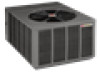
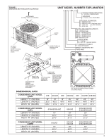
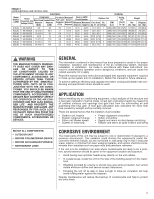
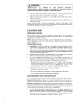
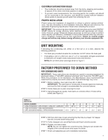
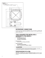
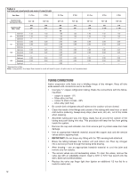
CUSTOMER SATISFACTION ISSUES • The condenser should be located away from the living, sleeping and recational spaces of the owner and those spaces on adjoining property. • To prevent noise transmissionm, the mounting pad for the outdoor unit should not be connected to the structure, and should be located sufficient distance above grade to prevent ground water from enteriing the unit. PROPER INSTALLATION Proper sizing and installation of equipment is critical to achieve optimal performance. Use the information in this Installation Instruction Manual and reference the applicable Engineering Specification Sheet when installing this product. IMPORTANT: This product has been designed and manufactured to meet ENERGY STAR® criteria for energy efficiency when matched with appropriate coil components. However, proper refrigerant charge and proper air flow are critical to achieve rated capacity and efficiency. Installation of this product should follow the manufacturer's refrigerant charging and air flow instructions. Failure to confirm proper charge and airflow may reduce energy efficiency and shorten equipment life. UNIT MOUNTING If elevating the condensing unit, either on a flat roof or on a slab, observe the following guidelines. • The base pan provided elevates the condenser coil 3/4" above the base pad. • If elevating a unit on a flat roof, use 4" x 4" (or equivalent) stringers positioned to distribute unit weight evenly and prevent noise and vibration. NOTE: Do not block drain openings shown in Figure 1. FACTORY-PREFERRED TIE-DOWN METHOD FOR CONDENSING UNITS IMPORTANT: These instructions are intended as a guide to securing equipment for wind-load ratings of "120 MPH sustained wind load" and "3-second, 150 MPH gust." While this procedure is not mandatory, the Manufacturer does recommend that equipment be properly secured in areas where high wind damage may occur. STEP 1: Before installing, clear pad of any dirt or debris. IMPORTANT: The pad must be constructed of industry-approved materials, and must be thick enough to accommodate the concrete fastener. STEP 2: Center base pan on pad, ensuring it is level. STEP 3: Using basepad as a guide, mark spots on concrete where 4 holes will be drilled (see Figure 2). TABLE 4 DIMENSIONS MODEL NUMBER L W A B C D (-)ANL-018/024/030, (-)APL-018/024, (-)ANL-031, (-)APM-018 375⁄8" 2515⁄16" 15" 34" 31⁄2" 221⁄2" (-)ANL-037/043/049, (-)ANL-036/042/048/060, (-)APL-030/036/042/048/060, (-)APM-024/030/036/042/048/060 411⁄2" 2913⁄16" 15" 38" 31⁄2" 261⁄2" S STEP 4: Drill four pilot holes in pad, ensuring that the hole is at least 1/4" deeper than the concrete screw being used. STEP 5: Center basepan over pre-drilled holes and insert concrete screws. STEP 6: Tighten concrete screws. NOTE: Do not over-tighten the concrete screws. Doing so can weaken the integrity of the concrete screw and cause it to break. STEP 7: Finish unit assembly per unit's installation instructions. 7
-
 1
1 -
 2
2 -
 3
3 -
 4
4 -
 5
5 -
 6
6 -
 7
7 -
 8
8 -
 9
9 -
 10
10 -
 11
11 -
 12
12 -
13
-
14
-
15
-
16
-
17
-
18
-
19
-
20
-
21
-
22
-
23
-
24
-
25
-
26
-
27
-
28
 |
 |