Rheem RAMP-JEZ Installation Instructions - Page 5
General, Application, Corrosive Environment
 |
View all Rheem RAMP-JEZ manuals
Add to My Manuals
Save this manual to your list of manuals |
Page 5 highlights
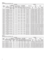
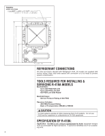
TABLE 3 (-)APM ELECTRICAL AND PHYSICAL DATA ELECTRICAL PHYSICAL Model Number (-)APM- Phase Frequency (Hz) Voltage (Volts) Compressor Rated Load Locked Rotor Amperes Amperes Fan Motor Full Load Amperes Minimum Circuit Ampacity Fuse or HACR Circuit Breaker Minimum Maximum Outdoor Coil Face Area No. CFM {RLA) (LRA) (FLA) Amperes Amperes Amperes Sq. Ft. [m2] Rows [L/s] Refrig. Per Circuit Oz. [g] Weight Net Shipping Lbs. [kg] Lbs. [kg] 018JAZ 1-60-208/230 9/9 48 024JAZ 1-60-208/230 13.5/13.5 58.3 030JAZ 1-60-208/230 12.8/12.8 64 036JAZ 1-60-208/230 16/16 79 042JAZ 1-60-208/230 17.9/17.9 112 048JAZ 1-60-208/230 21.8/21.8 117 060JAZ 1-60-208/230 26.4/26.4 134 0.8 13/13 15/15 20/20 11 [1.02] 1 2300 [1085] 82 [2325] 137[62.1] 152 [68.9] 1.1 18/18 25/25 30/30 20 [1.86] 1 3300 [1557] 128 [3629] 190 [86.2] 205 [93] 0.8 17/17 25/25 25/25 20 [1.86] 1 3300 [1557] 129 [3657] 200 [90.7] 213 [96.6] 0.8 21/21 25/25 35/35 23.01 [2.14] 1 3300 [1557] 146 [4139] 201 [91.2] 223 [101.2] 2.8 26/26 30/30 40/40 23.01 [2.14] 1 3300 [1557] 152 [4309] 224 [101.6] 246 [111.6] 2.8 31/31 40/40 50/50 23.01 [2.14] 2 3300 [1557] 203 [5755] 265 [120.2] 290 [131.5] 2.8 36/36 45/45 60/60 23 [2.14] 2 3300 [1557] 262 [7428] 274 [124.3] 299 [135.6] ! WARNING THE MANUFACTURER'S WARRANTY DOES NOT COVER ANY DAMAGE OR DEFECT TO THE AIR CONDITIONER CAUSED BY THE ATTACHMENT OR USE OF ANY COMPONENTS. ACCESSORIES OR DEVICES (OTHER THAN THOSE AUTHORIZED BY THE MANUFACTURER) INTO, ONTO OR IN CONJUNCTION WITH THE AIR CONDITIONER. YOU SHOULD BE AWARE THAT THE USE OF UNAUTHORIZED COMPONENTS, ACCESSORIES OR DEVICES MAY ADVERSELY AFFECT THE OPERATION OF THE AIR CONDITIONER AND MAY ALSO ENDANGER LIFE AND PROPERTY. THE MANUFACTURER DISCLAIMS ANY RESPONSIBILITY FOR SUCH LOSS OR INJURY RESULTING FROM THE USE OF SUCH UNAUTHORIZED COMPONENTS, ACCESSORIES OR DEVICES. GENERAL The information contained in this manual has been prepared to assist in the proper installation, operation and maintenance of the air conditioning system. Improper installation, or installation not made in accordance with these instructions, can result in unsatisfactory operation and/or dangerous conditions, and can cause the related warranty not to apply. Read this manual and any instructions packaged with separate equipment required to make up the system prior to installation. Retain this manual for future reference. To achieve optimum efficiency and capacity, the indoor cooling coils listed in the condensing unit specification sheet should be used. APPLICATION Before installing any air conditioning equipment, a duct analysis of the structure and a heat gain calculation must be made. A heat gain calculation begins by measuring all external surfaces and openings that gain heat from the surrounding air and quantifying that heat gain. A heat gain calculation also calculates the extra heat load caused by sunlight and by humidity removal. There are several factors that the installers must consider: • Outdoor unit location • System refrigerant charge • Indoor unit blower speed • System air balancing • Proper equipment evacuation • Indoor unit airflow • Supply and return air duct design and sizing • Diffuser and return air grille location and sizing MATCH ALL COMPONENTS: • OUTDOOR UNIT • INDOOR COIL/METERING DEVICE • INDOOR AIR HANDLER/FURNACE • REFRIGERANT LINES CORROSIVE ENVIRONMENT The metal parts of this unit may be subject to rust or deterioration if exposed to a corrosive environment. This oxidation could shorten the equipment's useful life. Corrosive elements include, but are not limited to, salt spray, fog or mist in seacoast areas, sulphur or chlorine from lawn watering systems, and various chemical contaminants from industries such as paper mills and petroleum refineries. If the unit is to be installed in an area where contaminants are likely to be a problem, special attention should be given to the equipment location and exposure. • Avoid having lawn sprinkler heads spray directly on the unit cabinet. • In coastal areas, locate the unit on the side of the building away from the waterfront. • Shielding provided by a fence or shrubs may give some protection, but cannot violate minimum airflow and service access clearances. • Elevating the unit off its slab or base enough to allow air circulation will help avoid holding water against the basepan. Regular maintenance will reduce the build-up of contaminants and help to protect the unit's finish. 5
-
 1
1 -
 2
2 -
 3
3 -
 4
4 -
 5
5 -
 6
6 -
 7
7 -
 8
8 -
 9
9 -
 10
10 -
 11
11 -
12
-
13
-
14
-
15
-
16
-
17
-
18
-
19
-
20
-
21
-
22
-
23
-
24
-
25
-
26
-
27
-
28
 |
 |