Rheem RAMP-JEZ Installation Instructions - Page 17
Warning
 |
View all Rheem RAMP-JEZ manuals
Add to My Manuals
Save this manual to your list of manuals |
Page 17 highlights
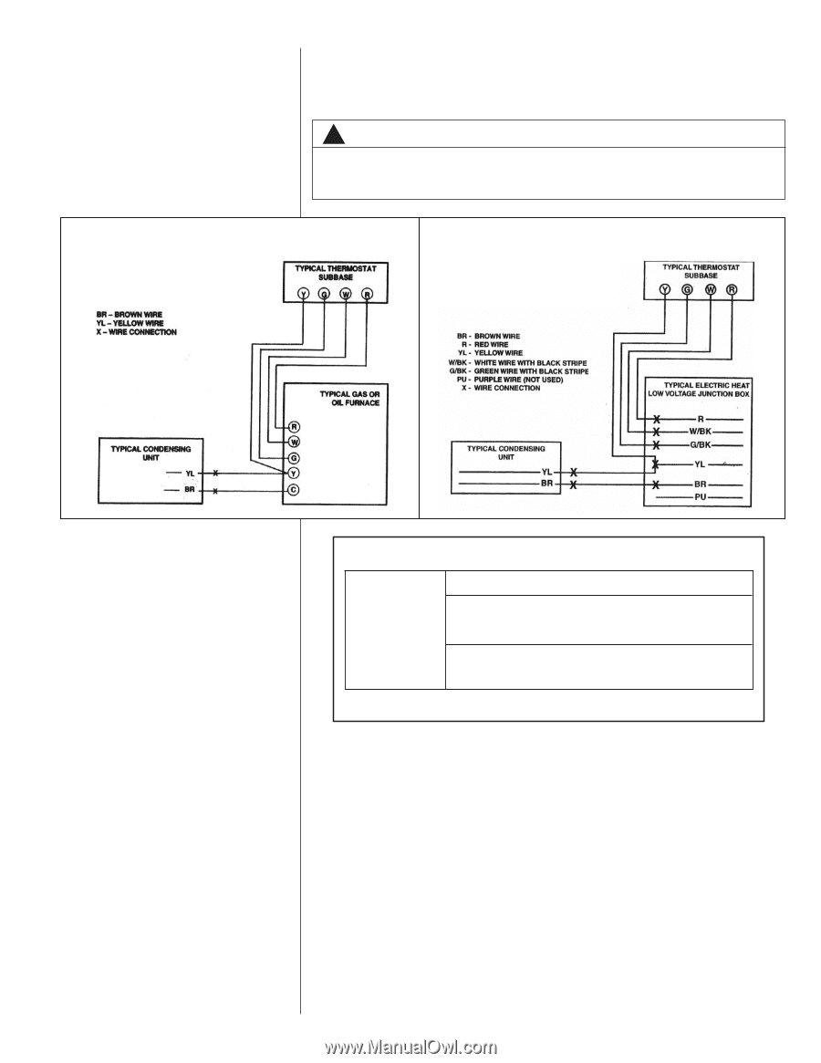
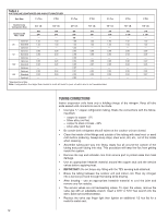
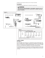
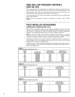
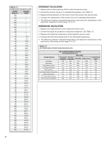
DO NOT connect aluminum field wire to the contactor terminals. GROUNDING A grounding lug is provided near the contactor for a ground wire. ! WARNING THE UNIT MUST BE PERMANENTLY GROUNDED. FAILURE TO DO SO CAN CAUSE ELECTRICAL SHOCK RESULTING IN SEVERE PERSONAL INJURY OR DEATH. FIGURE 3 CONTROL WIRING FOR GAS OR ELECTRIC HEAT FOR TYPICAL GAS OR OIL HEAT FOR TYPICAL ELECTRIC HEAT TABLE 8 FIELD WIRE SIZE FOR 24 VOLT THERMOSTAT CIRCUITS Thermostat Load - Amps SOLID COPPER WIRE - AWG. 3.0 16 14 12 10 10 10 2.5 16 14 12 12 10 10 2.0 18 16 14 12 12 10 50 100 150 200 250 300 Length of Run - Feet (1) (1) Wire length equals twice the run distance. NOTE: Do not use control wiring smaller than No. 18 AWG between thermostat and outdoor unit. CONTROL WIRING (See Figure 4) If the low voltage control wiring is run in conduit with the power supply, Class I insulation is required. Class II insulation is required if run separate. Low voltage wiring may be run through the insulated bushing provided in the 7/8 hole in the base panel, up to and attached to the pigtails from the bottom of the control box. Conduit can be run to the base panel if desired by removing the insulated bushing. A thermostat and a 24 volt, 40 VA minimum transformer are required for the control circuit of the condensing unit. The furnace or the air handler transformer may be used if sufficient. See the wiring diagram for reference. Use Table 8 to size the 24 volt control wiring. 17
-
 1
1 -
2
-
3
-
4
-
5
-
6
-
7
-
8
-
9
-
10
-
11
-
 12
12 -
 13
13 -
 14
14 -
 15
15 -
 16
16 -
 17
17 -
 18
18 -
 19
19 -
 20
20 -
 21
21 -
 22
22 -
23
-
24
-
25
-
26
-
27
-
28
 |
 |