Rheem RAMP-JEZ Installation Instructions - Page 22
Superheat Calculation, Subcooling Calculation
 |
View all Rheem RAMP-JEZ manuals
Add to My Manuals
Save this manual to your list of manuals |
Page 22 highlights
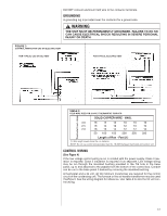
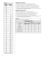
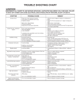
TTAABBLLEE192 TTEEMMPPEERRAATTUURREEPPRREESSSSUURE CHART TEMP (Deg. F) R-410A PSIG -150 - -140 - -130 - -120 - -110 - -100 - -90 - -80 - -70 - -60 0.4 -50 5.1 -40 10.9 -35 14.2 -30 17.9 -25 22.0 -20 26.4 -15 31.3 -10 36.5 -5 42.2 0 48.4 5 55.1 10 62.4 15 70.2 20 78.5 25 87.5 30 97.2 35 107.5 40 118.5 45 130.2 50 142.7 55 156.0 60 170.1 65 185.1 70 201.0 75 217.8 80 235.6 85 254.5 90 274.3 95 295.3 100 317.4 105 340.6 110 365.1 115 390.9 120 418.0 125 446.5 130 476.5 135 508.0 140 541.2 145 576.0 150 612.8 22 SUPERHEAT CALCULATION 1. Measure the suction pressure at the suction line service valve. 2. Convert the suction pressure to saturated temperature. See TTable 91.2. 3. Measure the temperature of the suction line at the suction line service valve. 4. Compare the temperature of the suction line to the saturated temperature. 5. The difference between saturated temperature and suctin line temperature is the superheat. Superheat normal range 12° to 15°. SUBCOOLING CALCULATION 1. Measure the liquid pressure at the liquid line service valve. 2. Convert the liquid line pressure to ssaattuurraatteedd tteemmppeerratuturere. .SSeeeeTTaabblele1130. . 3. Measure the liquid line temperature at the liquid line service valve. 4. Compare the liquid line temperature to the saturated temperature. 5. The difference between saturated temperature and liquid line temperature is the subcooling. Subcooling normal range 9° to 12°. TAABBLLEE 1130 AIR CONDITIONING SYSTEM TTRROOUUBBLLEESSHHOOOOTTIINNGGTTIIPPSS AIR CONDITIONING SYSTEM TROUBLESHOOTING TIPS SYSTEM PROBLEM INDICATORS DISCHARGE PRESSURE SUCTION PRESSURE SUPERHEAT SUBCOOLING COMPRESSOR AMPS Overcharge High High Low High High Undercharge Low Low High Low Low Liquid Restriction (Drier) Low Low High High Low Low Evaporator Airflow Low Low Low Low Low Dirty Condenser High High Low Low High Low Outside Ambient Temperature Low Low High High Low Inefficient Compressor Low High High High Low TEV Feeler Bulb Charge Lost Low Low High High Low Poorly Insulated Sensing Bulb High High Low Low High
-
 1
1 -
2
-
3
-
4
-
5
-
6
-
7
-
8
-
9
-
10
-
11
-
12
-
13
-
14
-
15
-
16
-
 17
17 -
 18
18 -
 19
19 -
 20
20 -
 21
21 -
 22
22 -
 23
23 -
 24
24 -
 25
25 -
 26
26 -
 27
27 -
28
 |
 |