Rheem RAMP-JEZ Installation Instructions - Page 12
Tubing Connections
 |
View all Rheem RAMP-JEZ manuals
Add to My Manuals
Save this manual to your list of manuals |
Page 12 highlights
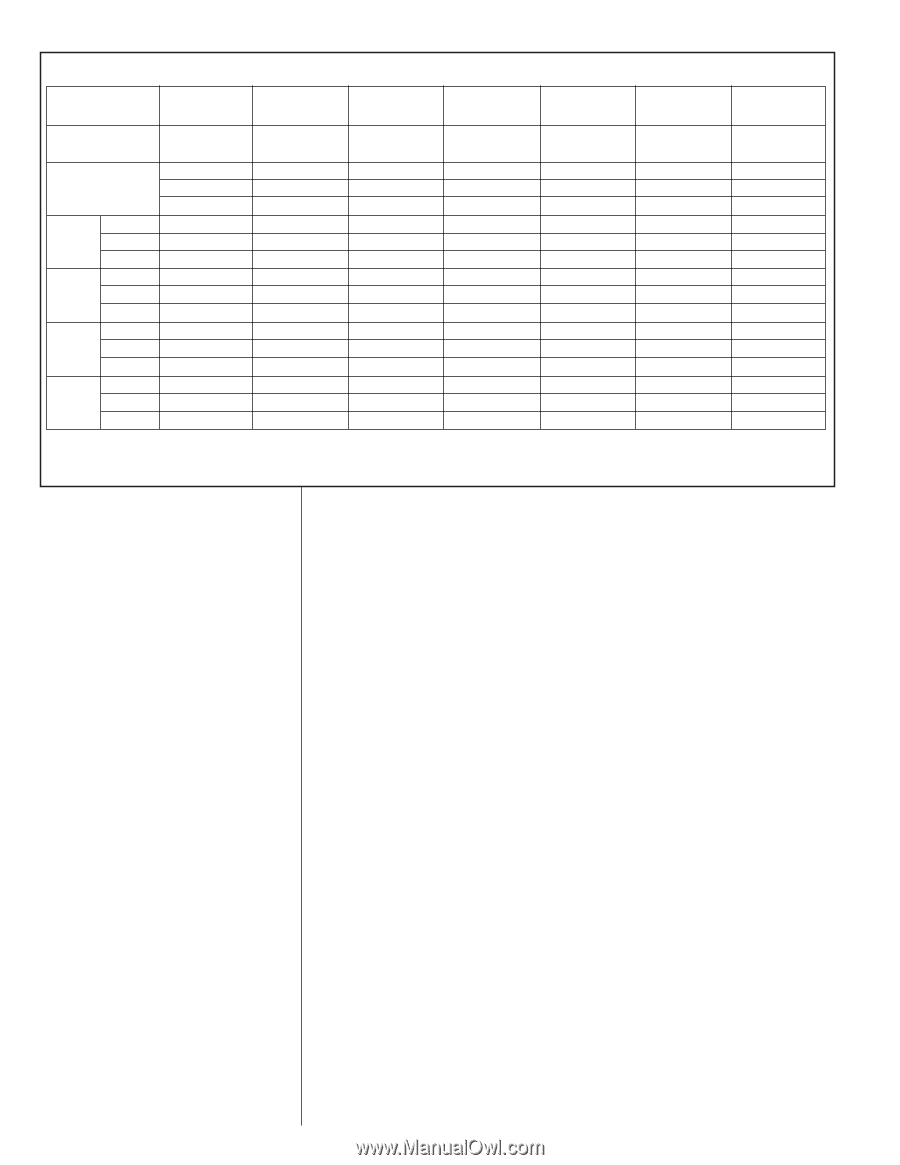
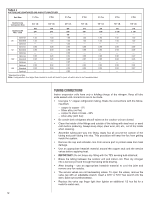
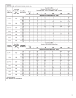
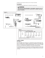
TABLE 5 SUCTION LINE LENGTH/SIZE AND CAPACITY MULTIPLIER Unit Size 11⁄2 Ton 2 Ton 21⁄2 Ton 3 Ton 31⁄2 Ton Suction Line Connection Size 3/4" I.D. 3/4" I.D. 3/4" I.D. 7/8" I.D. 7/8" I.D. Suction Line Run - Feet Optional 25' Standard Optional Optional 50' Standard Optional Optional 100' Standard Optional Optional 150' Standard Optional 5/8 3/4* - 1.00 1.00 - 0.98 0.99 - 0.95 0.96 - 0.92 0.93 - 5/8 3/4* - 1.00 1.00 - 0.98 0.99 - 0.95 0.96 - 0.92 0.94 - 5/8 3/4* 7/8 1.00 1.00 1.00 0.96 0.98 0.99 0.94 0.96 0.97 0.91 0.93 0.95 3/4 3/4 7/8* 7/8* - - 1.00 1.00 1.00 1.00 - - 0.98 0.99 0.99 0.99 - - 0.96 0.96 0.97 0.98 - - 0.94 0.94 0.95 0.96 - - *Standard Line Size Note: Using suction line larger than shown in chart will result in poor oil return and is not recommended. 4 Ton 7/8" I.D. 7/8 1 1/8* - 1.00 1.00 - 0.99 0.99 - 0.96 0.98 - 0.95 0.96 - 5 Ton 7/8" I.D. 7/8 1 1/8* - 1.00 1.00 - 0.99 0.99 - 0.97 0.98 - 0.94 0.97 - TUBING CONNECTIONS Indoor evaporator coils have only a holding charge of dry nitrogen. Keep all tube ends sealed until connections are to be made. • Use type "L" copper refrigeration tubing. Braze the connections with the following alloys: - copper to copper - 5% - Silver alloy (no flux) - copper to steel or brass - 35% - silver alloy (with flux) • Be certain both refrigerant shutoff valves at the outdoor unit are closed. • Clean the inside of the fittings and outside of the tubing with steel wool or sand cloth before soldering. Always keep chips, steel wool, dirt, etc., out of the inside when cleaning. • Assemble tubing part way into fitting. Apply flux all around the outside of the tubing and push tubing into stop. This procedure will keep the flux from getting inside the system. • Remove the cap and schrader core from service port to protect seals from heat damage. • Use an appropriate heatsink material around the copper stub and the service valves before applying heat. • IMPORTANT: Do not braze any fitting with the TEV sensing bulb attached. • Braze the tubing between the outdoor unit and indoor coil. Flow dry nitrogen into a service port and through the tubing while brazing. • After brazing - use an appropriate heatsink material to cool the joint and remove any flux residue. • The service valves are not backseating valves. To open the valves, remove the valve cap with an adjustable wrench. Insert a 3/16" or 5/16" hex wrench into the stem. Back out counterclockwise. • Replace the valve cap finger tight then tighten an additional 1/2 hex flat for a metal-to-metal seal. 12
-
 1
1 -
2
-
3
-
4
-
5
-
6
-
 7
7 -
 8
8 -
 9
9 -
 10
10 -
 11
11 -
 12
12 -
 13
13 -
 14
14 -
 15
15 -
 16
16 -
 17
17 -
18
-
19
-
20
-
21
-
22
-
23
-
24
-
25
-
26
-
27
-
28
 |
 |