Rheem RAMP-JEZ Installation Instructions - Page 16
Electrical Wiring
 |
View all Rheem RAMP-JEZ manuals
Add to My Manuals
Save this manual to your list of manuals |
Page 16 highlights
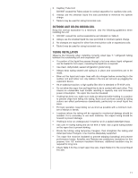
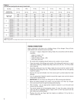
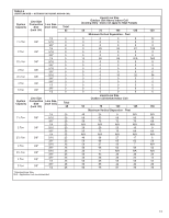
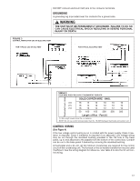
3. Read and record the indoor ambient wet bulb temperature entering the indoor coil. 4. Use the appropriate charging chart to compare the actual liquid pressure to the correct pressure as listed on the chart. 5. R-410A charging charts are listed on the unit. ! CAUTION R-410A PRESSURE ARE APPROXIMATELY 60% HIGHER THAN R-22 PRESSURES. USE APPROPRIATE CARE WHEN USING THIS REFRIGERANT. FAILURE TO EXERCISE CARE MAY RESULT IN EQUIPMENT DAMAGE, OR PERSONAL INJURY. CHARGING BY WEIGHT For a new installation, evacuation of interconnecting tubing and evaporator coil is adequate; otherwise, evacuate the entire system. Use the factory charge shown in Table 1 of these instructions or unit data plate. Note that charge value includes charge required for 15 ft. of standard size interconnecting liquid line. Calculate actual charge required with installed liquid line size and length using: 1/4" O.D. = 0.2 oz./ft. 5/16" O.D. = 0.3 oz./ft. 3/8" O.D. = 0.5 oz./ft. 1/2" O.D. = 1.0 oz./ft. With an accurate scale (+/- 1 oz.) or volumetric charging device, adjust charge difference between that shown on the unit data plate and that calculated for the new system installation. If the entire system has been evacuated, add the total calculated charge. NOTE: When the total refrigerant charge volume exceeds the values in Tables 1, 2 and 3, the manufacturer recommends installing a crankcase heater and start kit. FINAL LEAK TESTING After the unit has been properly evacuated and charged, a halogen leak detector should be used to detect leaks in the system. All piping within the condensing unit, evaporator, and interconnecting tubing should be checked for leaks. If a leak is detected, the refrigerant should be recovered before repairing the leak. The Clean Air Act prohibits venting refrigerant into the atmosphere. ELECTRICAL WIRING Field wiring must comply with the National Electric Code (C.E.C. in Canada) and any applicable local code. POWER WIRING It is important that proper electrical power from a commercial utility is available at the condensing unit contactor. Voltage ranges for operation are shown in Table 7. Install a branch circuit disconnect within sight of the unit and of adequate size to handle the starting current (see Tables 1 and 2). Power wiring must be run in a rain-tight conduit. Conduit must be run through the connector panel below the access cover (see Figure 1) and attached to the bottom of the control box. Connect power wiring to contactor located in outdoor condensing unit electrical box. (See wiring diagram attached to unit access panel.) Check all electrical connections, including factory wiring within the unit and make sure all connections are tight. TABLE 7 VOLTAGE RANGES (60 HZ) Nameplate Voltage 208/230 (1 Phase) 208/230 (3 Phase) 460 575 Operating Voltage Range at Copeland Maximum Load Design Conditions for Compressors 187 - 253 187 - 253 414 - 506 517 633 16
-
 1
1 -
2
-
3
-
4
-
5
-
6
-
7
-
8
-
9
-
10
-
 11
11 -
 12
12 -
 13
13 -
 14
14 -
 15
15 -
 16
16 -
 17
17 -
 18
18 -
 19
19 -
 20
20 -
 21
21 -
22
-
23
-
24
-
25
-
26
-
27
-
28
 |
 |