Ricoh Aficio GX e3300N User Guide - Page 704
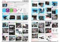
Carriage unit replacement procedure, Before, unlocking, After - gx ink collector unit
 |
View all Ricoh Aficio GX e3300N manuals
Add to My Manuals
Save this manual to your list of manuals |
Page 704 highlights
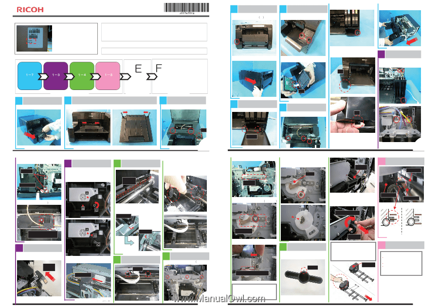
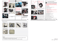
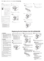
Carriage unit replacement procedure V.1.1 Before installing the unit Caution Be sure to install the carriage unit by the date printed on the bar code seal. If you do not, this can adversely affect the ink in the cartridges and the preservative liquid in the head tank, which can cause image quality problems. 1. Make sure to turn off the printer main power before beginning the replacement. 2. Do not touch the print head nozzle, as this may cause the print quality to decrease. 3. Do not touch the ink level feeler, as this may cause ink leaks. 4. If ink drips onto the belt, clean it off with a soft cloth. Accessories Refer to the Appendix: Accessories. Following is the overall carriage units replacement flow. ABCD Ჿ 䋱䋭䋷 䋱䋭䋳 䋱䋭䋴 䋱䋭䋳 Remove covers Release ink supply unit Release guide rod Remove Carriage unit Remove carriage unit Attach carriage unit A-1 Remove paper tray A-2 Remove output tray Remove the paper tray. Remove the output tray by pushing the hinges on both sides. ųųųųų1. Reset NVs 2. Set new print head ranks ųųųųų3. Ink initialization ųųųųų4. Nozzle check ųųųųų5. Adjust print head position ųųųųų6. Adjust registration ųųųųų7. Adjust paper feed ųųųųų8. Print color demo chart/SMC Adjustment A-3 Remove inner/upper covers Remove the screws (x2), tab. A-4 Remove right cover 1. Remove the screw 䋨x1䋩. A-6 Remove operation panel 2. Remove the screw (x1). 1. Remove the screws (x2). 4. Pull out the cover. 2. Slide the right cover backward. 2. Remove the FFC. 3. Release the tab on the front left corner of the machine. Tab B-1 Release ink supply unit 1. Remove the ink cartridges. 2. Remove the screws (x3). FFC A-5 Remove ink cartridge cover Unlock the hinges. A-7 Remove front cover 1. Loosen the screws (x3). Tab 3. Remove the clamps and connector. B -3 Release carriage C -1 Remove encoder strip Clamp Connector 1. Insert the tip of a screwdriver into the hole [C] and turn it counterclockwise until the two triangle marks ([A] and [B]) are aligned. Encoder strip 4. Remove the screw (x1䋩. Before Ჽ unlocking Disconnect the right side and left side next. Pull the strip gently and lift it off its hook. Right side Tab Replacing Hinges t1he Ink Collector Insert the end of the tool into the 2. Remove the linkage. Unit GX hole. Fasten the rear end of the tool to the rear guide rod. Fasten the front end of the tool to the front guide rod. e3300/e5500 Linkage 5. Remove the screw, rotate the cam until the triangle marks are aligned, and then remove the cam. Cam Holder 2 D- Remove the belt from 1 carriage Upper belt ĭ Ĭ 3. Remove the guide lock 䋨screw x1䋩. 2. Slide the holder onto the end of the rod, and then rotate it 180 degrees to lock it in place. Finally, pull out the holder and rod together. Turn 180 degrees Carriage Lower belt Ink supply tube housing B Push carriage -2 position lever Set the carriage position lever to the rear position. Rear position After Ჽ unlocking 2. Push the carriage to the center. Carriage Left side C Attach the fastening -2 and removal tools Holes C -3 Unlock guide rod 1. Remove right stay plate 䋨screw x3). 3 Guide lock 4. Remove the spring. Do not touch this side C -4 Pull out guide rod 1. Attach the holder to the end of the guide rod. Boss Pull out CAUTION: Make sure to secure the carriage unit in place with one hand while you remove the guide rod with the other hand. Before After Carriage Before removing After removing D2 Remove carriage FFC CAUTION: 䊶Make sure not to touch the grease on the guide rod. 䊶Do not touch ink level feeler. 䊶Keep the carriage unit in the orientation shown in the photo (Do not rotate it or tip it sideways). CAUTION: Make sure to remove the spring by disconnecting the top end (shown by the arrow in the photo). Print head width 4
-
 1
1 -
2
-
3
-
4
-
5
-
6
-
7
-
8
-
9
-
10
-
11
-
12
-
13
-
14
-
15
-
16
-
17
-
18
-
19
-
20
-
21
-
22
-
23
-
24
-
25
-
26
-
27
-
28
-
29
-
30
-
31
-
32
-
33
-
34
-
35
-
36
-
37
-
38
-
39
-
40
-
41
-
42
-
43
-
44
-
45
-
46
-
47
-
48
-
49
-
50
-
51
-
52
-
53
-
54
-
55
-
56
-
57
-
58
-
59
-
60
-
61
-
62
-
63
-
64
-
65
-
66
-
67
-
68
-
69
-
70
-
71
-
72
-
73
-
74
-
75
-
76
-
77
-
78
-
79
-
80
-
81
-
82
-
83
-
84
-
85
-
86
-
87
-
88
-
89
-
90
-
91
-
92
-
93
-
94
-
95
-
96
-
97
-
98
-
99
-
100
-
101
-
102
-
103
-
104
-
105
-
106
-
107
-
108
-
109
-
110
-
111
-
112
-
113
-
114
-
115
-
116
-
117
-
118
-
119
-
120
-
121
-
122
-
123
-
124
-
125
-
126
-
127
-
128
-
129
-
130
-
131
-
132
-
133
-
134
-
135
-
136
-
137
-
138
-
139
-
140
-
141
-
142
-
143
-
144
-
145
-
146
-
147
-
148
-
149
-
150
-
151
-
152
-
153
-
154
-
155
-
156
-
157
-
158
-
159
-
160
-
161
-
162
-
163
-
164
-
165
-
166
-
167
-
168
-
169
-
170
-
171
-
172
-
173
-
174
-
175
-
176
-
177
-
178
-
179
-
180
-
181
-
182
-
183
-
184
-
185
-
186
-
187
-
188
-
189
-
190
-
191
-
192
-
193
-
194
-
195
-
196
-
197
-
198
-
199
-
200
-
201
-
202
-
203
-
204
-
205
-
206
-
207
-
208
-
209
-
210
-
211
-
212
-
213
-
214
-
215
-
216
-
217
-
218
-
219
-
220
-
221
-
222
-
223
-
224
-
225
-
226
-
227
-
228
-
229
-
230
-
231
-
232
-
233
-
234
-
235
-
236
-
237
-
238
-
239
-
240
-
241
-
242
-
243
-
244
-
245
-
246
-
247
-
248
-
249
-
250
-
251
-
252
-
253
-
254
-
255
-
256
-
257
-
258
-
259
-
260
-
261
-
262
-
263
-
264
-
265
-
266
-
267
-
268
-
269
-
270
-
271
-
272
-
273
-
274
-
275
-
276
-
277
-
278
-
279
-
280
-
281
-
282
-
283
-
284
-
285
-
286
-
287
-
288
-
289
-
290
-
291
-
292
-
293
-
294
-
295
-
296
-
297
-
298
-
299
-
300
-
301
-
302
-
303
-
304
-
305
-
306
-
307
-
308
-
309
-
310
-
311
-
312
-
313
-
314
-
315
-
316
-
317
-
318
-
319
-
320
-
321
-
322
-
323
-
324
-
325
-
326
-
327
-
328
-
329
-
330
-
331
-
332
-
333
-
334
-
335
-
336
-
337
-
338
-
339
-
340
-
341
-
342
-
343
-
344
-
345
-
346
-
347
-
348
-
349
-
350
-
351
-
352
-
353
-
354
-
355
-
356
-
357
-
358
-
359
-
360
-
361
-
362
-
363
-
364
-
365
-
366
-
367
-
368
-
369
-
370
-
371
-
372
-
373
-
374
-
375
-
376
-
377
-
378
-
379
-
380
-
381
-
382
-
383
-
384
-
385
-
386
-
387
-
388
-
389
-
390
-
391
-
392
-
393
-
394
-
395
-
396
-
397
-
398
-
399
-
400
-
401
-
402
-
403
-
404
-
405
-
406
-
407
-
408
-
409
-
410
-
411
-
412
-
413
-
414
-
415
-
416
-
417
-
418
-
419
-
420
-
421
-
422
-
423
-
424
-
425
-
426
-
427
-
428
-
429
-
430
-
431
-
432
-
433
-
434
-
435
-
436
-
437
-
438
-
439
-
440
-
441
-
442
-
443
-
444
-
445
-
446
-
447
-
448
-
449
-
450
-
451
-
452
-
453
-
454
-
455
-
456
-
457
-
458
-
459
-
460
-
461
-
462
-
463
-
464
-
465
-
466
-
467
-
468
-
469
-
470
-
471
-
472
-
473
-
474
-
475
-
476
-
477
-
478
-
479
-
480
-
481
-
482
-
483
-
484
-
485
-
486
-
487
-
488
-
489
-
490
-
491
-
492
-
493
-
494
-
495
-
496
-
497
-
498
-
499
-
500
-
501
-
502
-
503
-
504
-
505
-
506
-
507
-
508
-
509
-
510
-
511
-
512
-
513
-
514
-
515
-
516
-
517
-
518
-
519
-
520
-
521
-
522
-
523
-
524
-
525
-
526
-
527
-
528
-
529
-
530
-
531
-
532
-
533
-
534
-
535
-
536
-
537
-
538
-
539
-
540
-
541
-
542
-
543
-
544
-
545
-
546
-
547
-
548
-
549
-
550
-
551
-
552
-
553
-
554
-
555
-
556
-
557
-
558
-
559
-
560
-
561
-
562
-
563
-
564
-
565
-
566
-
567
-
568
-
569
-
570
-
571
-
572
-
573
-
574
-
575
-
576
-
577
-
578
-
579
-
580
-
581
-
582
-
583
-
584
-
585
-
586
-
587
-
588
-
589
-
590
-
591
-
592
-
593
-
594
-
595
-
596
-
597
-
598
-
599
-
600
-
601
-
602
-
603
-
604
-
605
-
606
-
607
-
608
-
609
-
610
-
611
-
612
-
613
-
614
-
615
-
616
-
617
-
618
-
619
-
620
-
621
-
622
-
623
-
624
-
625
-
626
-
627
-
628
-
629
-
630
-
631
-
632
-
633
-
634
-
635
-
636
-
637
-
638
-
639
-
640
-
641
-
642
-
643
-
644
-
645
-
646
-
647
-
648
-
649
-
650
-
651
-
652
-
653
-
654
-
655
-
656
-
657
-
658
-
659
-
660
-
661
-
662
-
663
-
664
-
665
-
666
-
667
-
668
-
669
-
670
-
671
-
672
-
673
-
674
-
675
-
676
-
677
-
678
-
679
-
680
-
681
-
682
-
683
-
684
-
685
-
686
-
687
-
688
-
689
-
690
-
691
-
692
-
693
-
694
-
695
-
696
-
697
-
698
-
 699
699 -
 700
700 -
 701
701 -
 702
702 -
 703
703 -
 704
704 -
 705
705 -
 706
706
 |
 |