Ricoh Aficio MP 2851 Security Target - Page 11
Hardware configuration of TOE, Operation Panel Unit hereafter Operation Panel, Engine - instructions
 |
View all Ricoh Aficio MP 2851 manuals
Add to My Manuals
Save this manual to your list of manuals |
Page 11 highlights
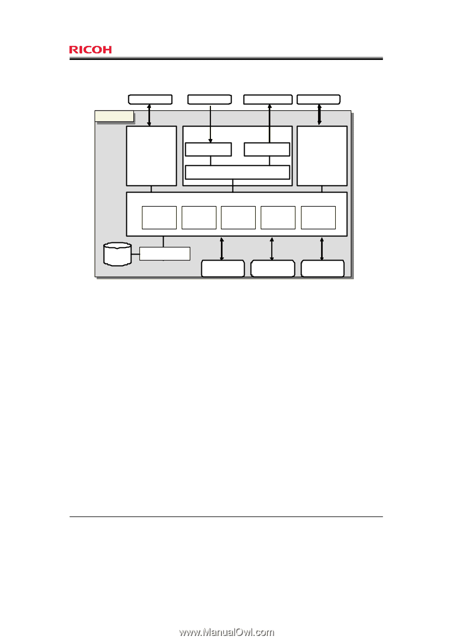
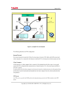
Page 11 of 81 User Document Output Document Telephone Line TTOOEE Engine Unit Operation Panel Unit Scanner Engine Printer Engine Engine Control Board Fax Unit * Optional Processor Controller Board RAM NVRAM Ic Key FlashROM HDD Ic Hdd Network Unit USB Port SD Card Slot Figure 2: Hardware configuration of TOE Operation Panel Unit (hereafter "Operation Panel ") The Operation Panel is an interface device that is installed on the TOE for use by users. It features key switches, LED indicators, an LCD touch screen, and the Operation Panel Control Board. The Operation Panel Control Software is installed in the Operation Panel Control Board. The Operation Panel Control Software controls the LEDs and displays information on the LCD touch screen after input information has been sent from the key switches and LCD touch screen to the MFP Control Software, or in response to direct instructions from the MFP Control Software. Engine Unit The Engine Unit contains a Scanner Engine, Printer Engine, and the Engine Control Board. The Scanner Engine is an input device to read the paper documents. The Printer Engine is an output device for printing and outputting of paper documents. The Engine Control Software is installed in the Engine Control Board. The Engine Control Software sends information about the status of the Scanner Engine and Printer Engine to the MFP Control Software, and operates the Scanner Engine or Printer Engine according to instructions from the MFP Control Software. Copyright (c) 2010 RICOH COMPANY, LTD. All Rights Reserved.
-
 1
1 -
2
-
3
-
4
-
5
-
 6
6 -
 7
7 -
 8
8 -
 9
9 -
 10
10 -
 11
11 -
 12
12 -
 13
13 -
 14
14 -
 15
15 -
 16
16 -
17
-
18
-
19
-
20
-
21
-
22
-
23
-
24
-
25
-
26
-
27
-
28
-
29
-
30
-
31
-
32
-
33
-
34
-
35
-
36
-
37
-
38
-
39
-
40
-
41
-
42
-
43
-
44
-
45
-
46
-
47
-
48
-
49
-
50
-
51
-
52
-
53
-
54
-
55
-
56
-
57
-
58
-
59
-
60
-
61
-
62
-
63
-
64
-
65
-
66
-
67
-
68
-
69
-
70
-
71
-
72
-
73
-
74
-
75
-
76
-
77
-
78
-
79
-
80
-
81
 |
 |