Ridgid LM-100 Owners Manual - Page 8
Laser Classification, FCC Statement, LCD Display Icons - micro manual
 |
View all Ridgid LM-100 manuals
Add to My Manuals
Save this manual to your list of manuals |
Page 8 highlights
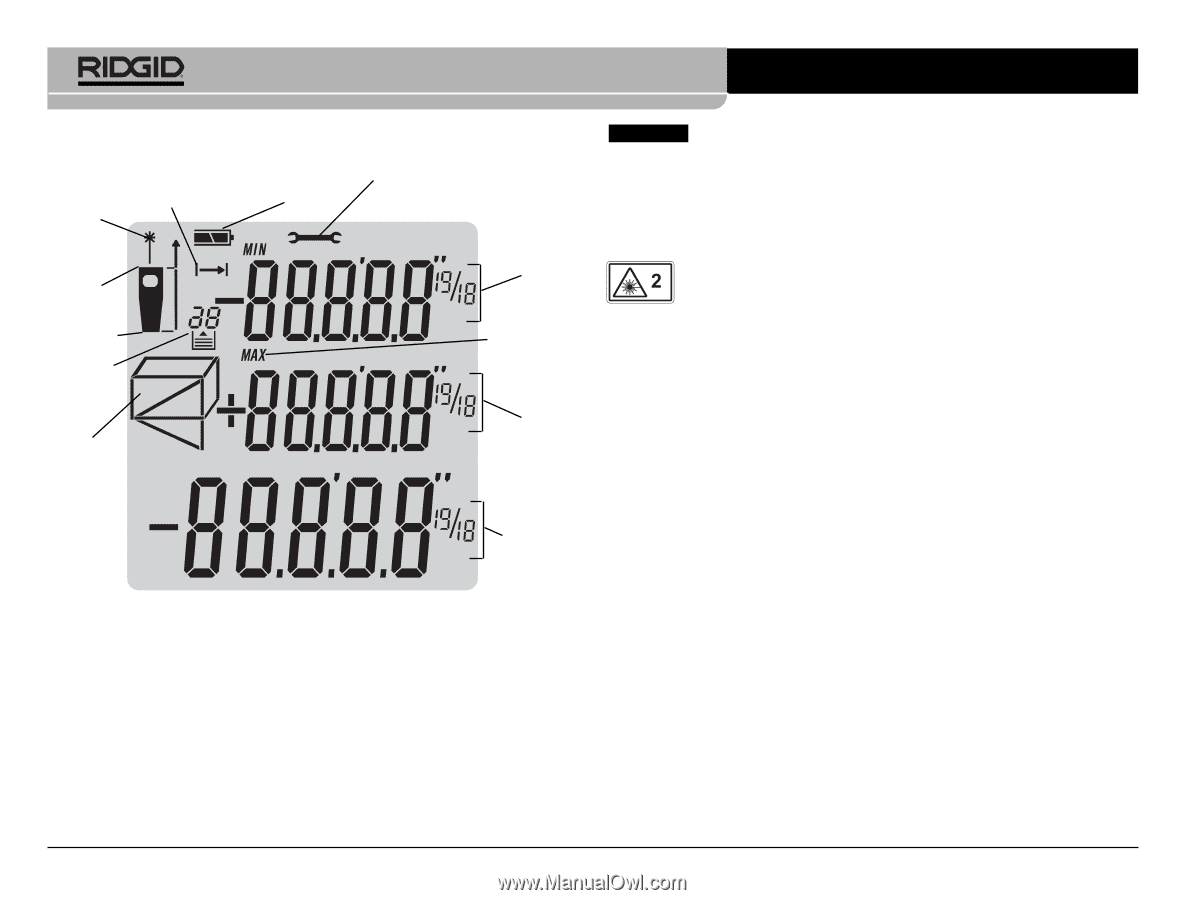
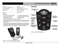
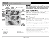
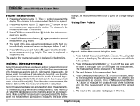
micro LM-100 Laser Distance Meter LCD Display Icons Laser Active Single Measurement Battery Indicator Reference Top Reference Bottom Memory Location Measuring Functions Figure 3 - micro LM-100 LCD Display Standard Equipment • micro LM-100 • Carrying Case • Wrist Strap Device Malfunction NOTICE This equipment is used to make distance measurements. Incorrect use or improper application may result in incorrect or inaccurate measurements. Selection of appropriate measurement methods for the conditions is the responsibility of the user. Second Prior Measurement Laser Classification The RIDGID micro LM-100 generates a visible laser beam that is emitted from the top of the device. Min Max (Continuous) The device complies with class 2 lasers according to: EN 608251:1994/A11:1996/A2:2001/A1:2002 First Prior Measurement Single Measurement/Calculation Result • Batteries (2 AAA) • Operator's Manual FCC Statement This equipment has been tested and found to comply with the limits for a Class B digital device, pursuant to part 15 of the FCC Rules. These limits are designed to provide reasonable protection against harmful interference in a residential installation. This equipment generates, uses, and can radiate radio frequency energy and, if not installed and used in accordance with the instructions, may cause harmful interference to radio communications. However, there is no guarantee that interference will not occur in a particular installation. If this equipment does cause harmful interference to radio or television reception, which can be determined by turning the equipment off and on, the user is encouraged to try to correct the interference by one or more of the following measures: • Reorient or relocate the receiving antenna. • Increase the separation between the equipment and receiver. • Consult the dealer or an experienced radio/TV technician for help. 6 Ridge Tool Company
-
 1
1 -
2
-
 3
3 -
 4
4 -
 5
5 -
 6
6 -
 7
7 -
 8
8 -
 9
9 -
 10
10 -
 11
11 -
 12
12 -
 13
13 -
14
-
15
-
16
-
17
-
18
-
19
-
20
-
21
-
22
-
23
-
24
-
25
-
26
-
27
-
28
-
29
-
30
-
31
-
32
-
33
-
34
-
35
-
36
-
37
-
38
-
39
-
40
-
41
-
42
-
43
-
44
-
45
-
46
-
47
-
48
-
49
-
50
-
51
-
52
-
53
-
54
-
55
-
56
-
57
-
58
-
59
-
60
-
61
-
62
-
63
-
64
-
65
-
66
-
67
-
68
-
69
-
70
-
71
-
72
-
73
-
74
-
75
 |
 |