Samsung HLP5085W User Manual (ENGLISH) - Page 11
Connecting a DTV Set-Top Box, Connecting to Y, P, Connecting to DVI Digital Visual Interface, G, B - power
 |
View all Samsung HLP5085W manuals
Add to My Manuals
Save this manual to your list of manuals |
Page 11 highlights
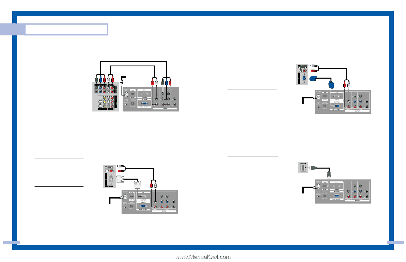
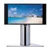
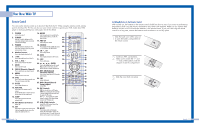
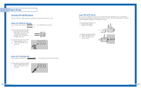
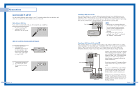
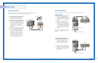
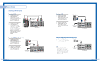
Connections Connecting a DTV Set-Top Box Connecting to Y,PB,PR 1 Connect a set of audio cables between the COMPONENT (1 or 2) AUDIO (L,R) IN jacks on the TV and the AUDIO OUT jacks on the Set-Top Box. 2 Connect a set of video cables between the COMPONENT (1 or 2) VIDEO (Y, PB, PR) IN jacks on the TV and VIDEO (Y/PB/PR or Y/CB/CR) OUT jacks on the Set-Top Box. Note: For an explanation of Component video, see your Set Top Box owner's manual. TV Rear Panel Incoming Cable or Antenna DTV Set-Top Box Connecting to DVI (Digital Visual Interface) 1 Connect a set of audio cables between the DVI AUDIO (L,R) IN jacks on the TV and the AUDIO OUT jacks on the Set-Top Box. TV Rear Panel 2 Connect a DVI video cable between the DVI IN jack on the TV and the DVI OUT jack on the Set-Top Box. Incoming Cable or Antenna DTV Set-Top Box English - 20 Connecting to R,G,B 1 Connect a set of audio cables between the PC AUDIO (L,R) IN jacks on the TV and the AUDIO OUT jacks on the Set-Top Box. 2 Connect a R,G,B video cable between the PC IN jack on the TV and the R.G.B OUT jack on the SetTop Box. TV Rear Panel Incoming Cable or Antenna DTV Set-Top Box Connecting to HDMI (High Definition Multimedia Interface) 1 Connect a HDMI cable between the HDMI IN jack on the TV and the HDMI OUT jack on the Set-Top Box. TV Rear Panel NOTE • Please check if the HDMI source's power is on, in case that you fail to select HDMI from the "Source List" even after you connected the cable of the HDMI source (DTV Set-Top Box, DVD, etc.) to TV. Incoming Cable or Antenna DTV Set-Top Box English - 21
-
 1
1 -
2
-
3
-
4
-
5
-
 6
6 -
 7
7 -
 8
8 -
 9
9 -
 10
10 -
 11
11 -
 12
12 -
 13
13 -
 14
14 -
 15
15 -
 16
16 -
17
-
18
-
19
-
20
-
21
-
22
-
23
-
24
-
25
-
26
-
27
-
28
-
29
-
30
-
31
-
32
-
33
-
34
-
35
-
36
-
37
-
38
-
39
-
40
-
41
-
42
-
43
-
44
-
45
-
46
-
47
-
48
 |
 |