Sanyo WF10 Instruction Manual, PLV-WF10 - Page 11
Connecting Projector
 |
UPC - 086483050046
View all Sanyo WF10 manuals
Add to My Manuals
Save this manual to your list of manuals |
Page 11 highlights
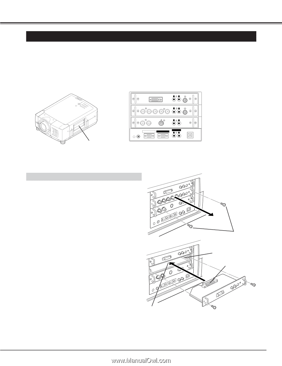
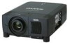
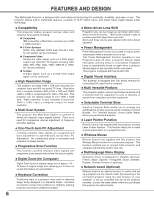
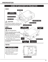
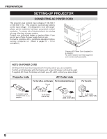
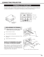
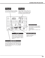
CONNECTING PROJECTOR TERMINALS OF PROJECTOR This projector applies various input/output terminals and 3 terminal slots for expansion to tune to diversity of signals from computers and video equipment. 3-built-in Terminal Slots enable you to arrange desired combinations of input sources just by changing Terminal Boards. For Terminal Boards, contact sales dealer where you purchased a projector. INPUT/OUTPUT TERMINALS 3 TERMINAL SLOTS (Factory set) AUDIO CONTROL PORT DVI R L R/Pr G/Y B/Pb H/HV V (MONO) AUDIO CONTROL PORT R L VIDEO/Y C S-VIDEO (MONO) AUDIO R L R/C JACK SERIAL PORT IN SERIAL PORT OUT (MONO) AUDIO OUT R L RESET (MONO) USB INPUT 3 INPUT 2 INPUT 1 DVI Terminal 5 BNC Terminal AV Terminal REPLACEMENT OF TERMINAL NOTE; When replacement of terminal board, MAIN ON/OFF switch should be OFF position. 1 Remove 2 Screws on terminal. 2 Pull out terminal by holding handle. 3 Replace terminal. Insert terminal along Guide to fit Plug into Socket. 4 Tighten screws to secure terminal. Screws Guide NOTES ON ORDERING OR USING Socket OPTIONAL INTERFACE BOARD When ordering or using Optional Interface Board (Terminal Board), contact your sales dealer. When contacting the sales dealer, tell the Optional Control Number (Op.cont.No.) in the menu that is located under Language Select Menu. (See page 39.) Plug Figure shows HDB 15-PIN terminal (Optional parts). 11
-
 1
1 -
2
-
3
-
4
-
5
-
 6
6 -
 7
7 -
 8
8 -
 9
9 -
 10
10 -
 11
11 -
 12
12 -
 13
13 -
 14
14 -
 15
15 -
 16
16 -
17
-
18
-
19
-
20
-
21
-
22
-
23
-
24
-
25
-
26
-
27
-
28
-
29
-
30
-
31
-
32
-
33
-
34
-
35
-
36
-
37
-
38
-
39
-
40
-
41
-
42
-
43
-
44
-
45
-
46
-
47
-
48
-
49
-
50
-
51
-
52
-
53
-
54
-
55
-
56
 |
 |