Sennheiser ew 300 G2 Instructions for Use - Page 58
Connecting the amplifier/mixing console, Service interface, rack adapter and antenna mount
 |
View all Sennheiser ew 300 G2 manuals
Add to My Manuals
Save this manual to your list of manuals |
Page 58 highlights
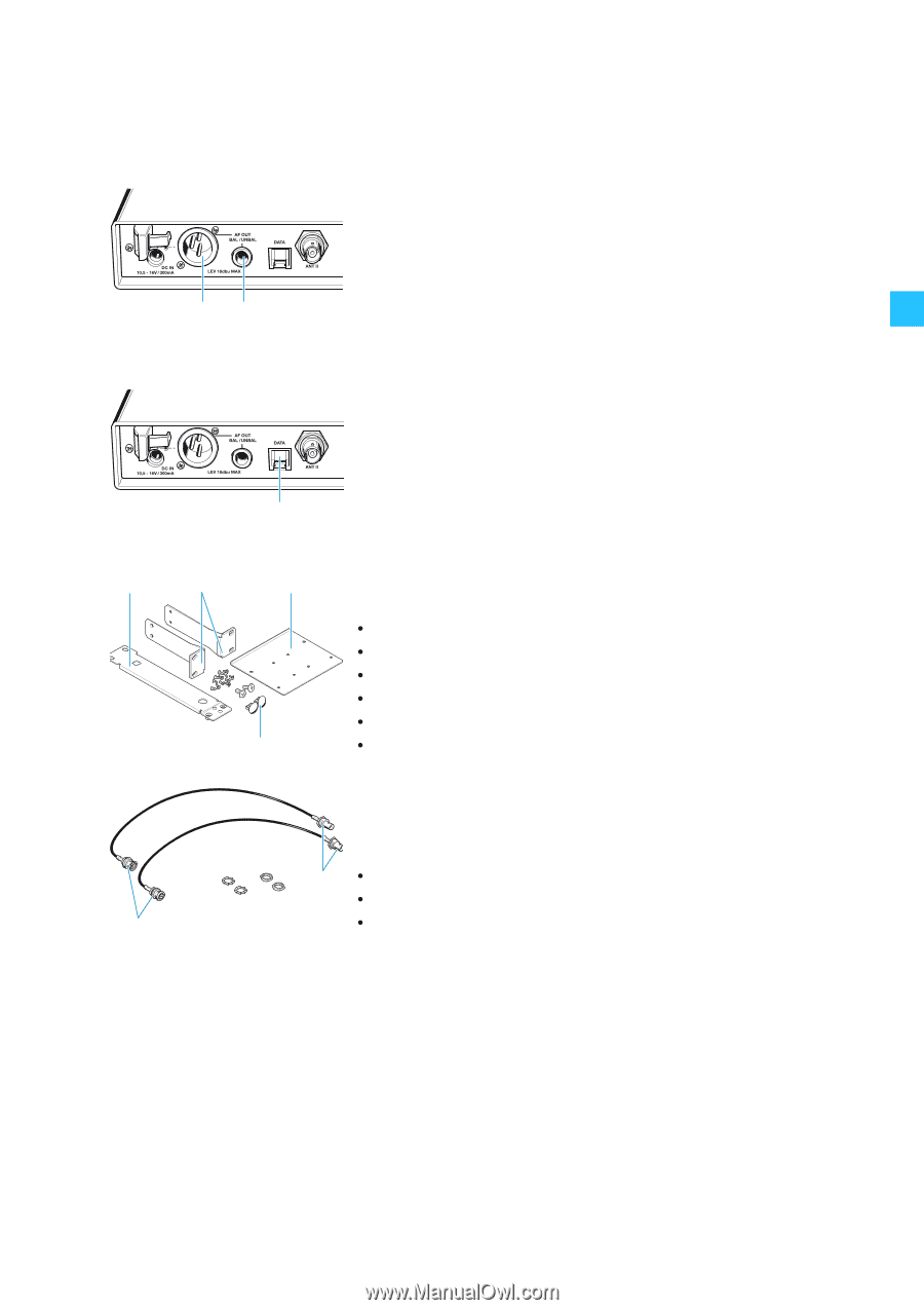
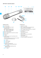
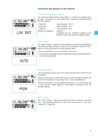
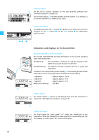
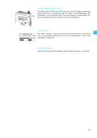
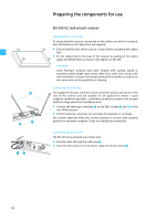
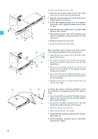
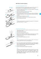
ᕧᕨ Connecting the amplifier/mixing console The EM 300 G2's audio outputs are available as an XLR-3M socket ¶ and a ¼" (6.3 mm) jack socket º, allowing you to simultaneously connect two units (e.g. amplifier, mixing console). The adjusted audio output level is common for both sockets. ̈ Connect the amplifier/mixing console to the XLR-3M socket ¶ or the ¼" (6.3 mm) jack socket º. For detailed information on balanced and unbalanced connection, please refer to the section "onnector assignment" on page 41. ̈ Via the operating menu, adapt the level of the audio output (AF OUT) to the input of the amplifier or mixing console (see "Adjusting the audio output level (EM 300 G2 only)" on page 31). Service interface The service interface ¾ is only required for servicing purposes. ᕩ 19" rack adapter and antenna mount ƺ ƹ ƻ For mounting one or two receivers into a 19" rack, you require the GA 2 rack adapter (available as an accessory). The GA 2 rack adapter consists of: y 2 rack mount "ears" ƹ y 1 connecting bar ƺ y 1 connecting plate ƻ y 2 covering plugs Ƽ for antenna holes y 12 recessed head screws M 3x6 Ƽ y 2 recessed head screws M 6x10 When mounting only one receiver into a rack, you can use the AM 2 antenna mount (available as an accessory) to mount the transmitter's antenna connection to the front of the GA 2 rack adapter. The AM 2 antenna mount consists of: ƽ y 2 BNC extension cables (screw-in BNC socket ƽ to BNC connector ƾ) y 2 plains washers ƾ y 2 nuts 13
-
 1
1 -
2
-
3
-
4
-
5
-
6
-
7
-
8
-
9
-
10
-
11
-
12
-
13
-
14
-
15
-
16
-
17
-
18
-
19
-
20
-
21
-
22
-
23
-
24
-
25
-
26
-
27
-
28
-
29
-
30
-
31
-
32
-
33
-
34
-
35
-
36
-
37
-
38
-
39
-
40
-
41
-
42
-
43
-
44
-
45
-
46
-
47
-
48
-
49
-
50
-
51
-
52
-
 53
53 -
 54
54 -
 55
55 -
 56
56 -
 57
57 -
 58
58 -
 59
59 -
 60
60 -
 61
61 -
 62
62 -
 63
63 -
64
-
65
-
66
-
67
-
68
-
69
-
70
-
71
-
72
-
73
-
74
-
75
-
76
-
77
-
78
-
79
-
80
-
81
-
82
-
83
-
84
-
85
-
86
-
87
-
88
-
89
-
90
-
91
-
92
-
93
-
94
-
95
-
96
-
97
-
98
-
99
-
100
-
101
-
102
-
103
-
104
-
105
-
106
-
107
-
108
-
109
-
110
-
111
-
112
-
113
-
114
-
115
-
116
-
117
-
118
-
119
-
120
-
121
-
122
-
123
-
124
-
125
-
126
-
127
-
128
-
129
-
130
-
131
-
132
-
133
-
134
-
135
-
136
-
137
-
138
-
139
-
140
-
141
-
142
-
143
-
144
-
145
-
146
-
147
-
148
-
149
-
150
-
151
-
152
-
153
-
154
-
155
-
156
-
157
-
158
-
159
-
160
-
161
-
162
-
163
-
164
-
165
-
166
-
167
-
168
-
169
-
170
-
171
-
172
-
173
-
174
-
175
-
176
-
177
-
178
-
179
-
180
 |
 |