Sharp A260 Service Manual
Sharp A260 - UX B/W Thermal Transfer Manual
 |
UPC - 074000033733
View all Sharp A260 manuals
Add to My Manuals
Save this manual to your list of manuals |
Sharp A260 manual content summary:
- Sharp A260 | Service Manual - Page 1
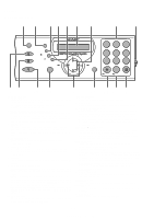
1. GENERAL DESCRIPTION [1] Specifications 1-1 [2] Operation panel 1-2 [3] Refer to the service manual of UX-P100U. [4] Refer to the service manual of UX-P100U. [5] Quick setup guide 1-3 [6] Quick reference guide 1-4 [7] Option imaging film specifications (UX-5CR 1-4 CHAPTER 2. ADJUSTMENTS - Sharp A260 | Service Manual - Page 2
UX-A260U CAUTION FOR BATTERY REPLACEMENT (Danish) ADVARSEL ! Lithiumbatteri-Eksplosionsfare ved fejlagtig le constructeur. Mettre au rébut les batteries usagées conformément aux instructions du fabricant. (Swedish) VARNING Explosionsfare vid felaktigt batteribyte. Använd samma batterityp - Sharp A260 | Service Manual - Page 3
film: Initial starter roll: (included with machine): 32 ft. (10 m) (approx. 30 letter-size pages) Replacement roll (not included): UX copier lb. Copy Bond UX-A260U Compatibility: (140 to 279 mm) Manual feeding: Width: 5.8 to FAX 60 Hz Operating temperature: 41 Based on Sharp Standard No SHARP - Sharp A260 | Service Manual - Page 4
FLASH key This key is used for Call Waiting and other special services that require subscription from your phone company. Your phone company will quick reference guide to the operation of your fax machine. This key is also used after dialing to poll (request fax transmission from) another machine. 12 - Sharp A260 | Service Manual - Page 5
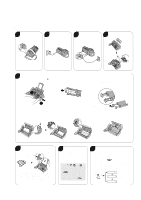
Refer to the service manual of UX-P100U. [5] Quick setup guide 1 Connect the handset and place it on the handset rest. Note: To enter your name and fax number and set the date and time so that they appear at the top of each fax you send, see pages 17 - 20 of your operation manual. 2 Plug the - Sharp A260 | Service Manual - Page 6
or press . SPEAKER 2. Dial the fax number. (UX-5CR) 1. Structure This article is composed of polyester film coated with heat-resistant layer, matt layer and hot melt ink layer, leader film and paper core. Ink film specification is "DNP standard ink film HC". 1 2 3 4 3. Wait for the reception - Sharp A260 | Service Manual - Page 7
UX-A260U CHAPTER 2. ADJUSTMENTS [1] Adjustments General Since the following adjustments and settings are provided for this model, make adjustments and/or setup as necessary. 1. Adjustments of output voltage (FACTORY ONLY) 1. Install the power supply unit in the machine ICs and electronic circuits - Sharp A260 | Service Manual - Page 8
UX-A260U [2] Diagnostics and service soft switch 1. Operating procedure (1) Entering the diagnostic mode Press FUNC → 9 → → 8 → # keys are tested. Result list is output. Check pattern is output. Various signals of FAX communication are output. Back-up memory is cleared, and is set at delivery. - Sharp A260 | Service Manual - Page 9
operation B B B B B B B B B B BB UX-A260U 3. 6. Signal send mode This mode is used to send various signals to the circuit during FAX communication. Every push of START machine and make the other machine copy the registered content. Before sending in this mode, it is necessary to set the other machine - Sharp A260 | Service Manual - Page 10
machine must be in the entry data send mode. After receiving is completed, the following lists are printed. 1. Telephone list data 2. Sender register data (*) 3. Optional setting list (*) 4. Soft switch content 5. Junk fax When the unit enters this mode, the check is started. *Operation of hardware - Sharp A260 | Service Manual - Page 11
UX-A260U 5. Soft switch description • Soft switch SW DATA NO. NO. ITEM Switch setting and 3 No. 4 1 1 1 0 7.2km 0 0 0 1 0 1 0km 5 for Caller ID) 6 No. 5 1 No. 6 1 0 0 0 0 7 Error criterion 10 ~ 20 % 5 ~ 10 % 0 8 Anti junk fax check Yes No 1 Remarks OPTION 2 - 5 - Sharp A260 | Service Manual - Page 12
UX-A260U SW DATA NO. NO. ITEM 1 Reserved 2 End Buzzer Yes 3 Disconnect the line when DIS is received in No RX mode SW 4 Equalizer freeze control (MODEM) On l A6 5 Equalizer freeze control 7200 BPS only No 6 CNG transmission in manual Dial pulse make/break ratio (%) B4 6 Reserved - Sharp A260 | Service Manual - Page 13
UX-A260U SW DATA NO. NO. ITEM Switch setting and function 1 0 1 DTMF signal transmission level (High) Binary input 2 No. 4 2 1 3 1 2 3 4 4 0 1 0 0 SW l 5 Automatic switching manual to auto receive Reception after 5 rings D1 mode No reception 6 Reserved Cl detect frequency 7 No.7 - Sharp A260 | Service Manual - Page 14
UX-A260U SW DATA NO. NO. 1 Reserved ITEM Switch setting and function 1 0 2 Protection of remote reception (5 ) detect Yes SW l 4 Remote reception with GE telephone Compatible F1 5 Remote operation code figure by external Binary input No Not compatible 6 TEL (0~9) No. = 8 4 2 1 7 - Sharp A260 | Service Manual - Page 15
UX-A260U SW DATA NO. NO. ITEM 1 Reserved 2 Reserved 3 SW 4 l G2 5 6 Reserved Reserved Reserved Reserved 7 8 Busy tone detect intermittent sound detect Busy tone detection pulse number 1 2 3 Fax switching when A.M. full SW 4 Busy tone detect continuation sound detect l frequency H2 - Sharp A260 | Service Manual - Page 16
UX-A260U SW DATA NO. NO. ITEM 1 A.M. quiet detect time 2 3 SW 4 l 5 I2 CPC detection time 6 7 8 1 Reserved 2 Max OGM record time 3 Two way record function SW 4 Toll - Sharp A260 | Service Manual - Page 17
) 8 1 Reserved 2 Reserved 3 Reserved SW 4 Reserved l L1 5 Cut off mode (COPY mode) 6 A4 paper enable 7 LEGAL & LETTER paper enable 8 Reserved UX-A260U Switch setting and function 1 0 Initial setting 0 0 Cannot change Change allowed 0 0 0 No Yes 1 No. 7 Off Low Middle High - Sharp A260 | Service Manual - Page 18
UX-A260U SW DATA NO. NO. ITEM Paper set size 1 No. 1 2 No. 2 3 SW l L2 4 5 Automatic reduce of receive Print contrast Auto No. 4 No. 5 6 No. 6 7 Reception reduction ratio in case of memory ful 100 % 8 Reserved 1 Reserved 2 Reserved 3 Reserved SW 4 Reserved l M1 5 Reserved 6 Reserved - Sharp A260 | Service Manual - Page 19
8 Reserved 1 Reserved 2 Reserved 3 Reserved SW l 4 Reserved O6 5 Reserved 6 Reserved 7 Reserved 8 Reserved ITEM Switch setting and function 1 0 UX-A260U Initial setting 0 0 0 0 0 0 0 0 0 0 0 0 0 0 0 0 0 0 0 0 0 0 0 0 0 0 0 0 0 0 0 0 0 0 0 0 0 0 0 0 0 0 0 0 0 0 0 0 Remarks 2 - 13 - Sharp A260 | Service Manual - Page 20
UX machine sends or does not send the signal (CSI signal) informing its own telephone No. to the remote fax machine act as an echo suppression switch, causing a communication problem. Though SW-A3 No. 1 and No. 2 communication can be checked, in case of trouble, without using a G3 tester or other - Sharp A260 | Service Manual - Page 21
switch is used to perform reception operation by fixing the equalizer control manual TX mode When set to "1", fax transmit the CNG signal in case of manual transmission mode (User press the START key after waiting for the fax if fax signal level is under -40dBm during reception, machine selects the - Sharp A260 | Service Manual - Page 22
UX to the user's choice. machine is set to answer after a large number of rings, it may not be able to receive faxes successfully. If you have difficulty receiving faxes, reduce the number of rings to a maximum of 6. SW-D1 No. 5 Automatic switching manual allows reception of services offered by USA - Sharp A260 | Service Manual - Page 23
remote reception. • If this soft SW is set to "1", other telephone sets may be adversely affected. UX-A260U SW-F1 No. 5 ~ No. 8 Remote operation code figure by external TEL (0 ~ 9) Remote operation codes can be changed from 0 through 9. If set to greater than 9, it defaults to 9. The "5 " is - Sharp A260 | Service Manual - Page 24
UX Fax switching when A.M. full If the answering machine's memory is full and there is no response, the machine automatically switches to Fax detect time Used to set no sound time (0 sec ~ 32 sec) during the T.A.D. mode operation. SW-I2 No. 6 ~ No. 8 CPC detection time Used to set the CPC (Calling - Sharp A260 | Service Manual - Page 25
ratio Troubleshooting Refer to the service manual of UX-P100U. [4] Error code table Refer to the service manual of UX-P100U. CHAPTER 3. MECHANISM BLOCKS [1] General description Refer to the service manual of UX-P100U. [2] Disassembly and assembly procedures Refer to the service manual of UX - Sharp A260 | Service Manual - Page 26
RECORDING PAPER THERMAL HEAD P-IN FILM SENSOR SENSOR FET IMAGING FILM PANEL I/F REGULATOR +24V OPERATION PPAANNEELL LCD STABILIZER HANDSET LINE SURGE PROTECT/ FILTER TEL/LIU PWB UNIT CML TRANSFORMER CI RECTIFIER TRANSFORMER RECTIFIER DIODE STURRAGNES ABSORBER POWER SUPPLY PWB - Sharp A260 | Service Manual - Page 27
15 CONTACT IMAGE SENSOR 7 LCD UNIT 14 CNLCD OPERATION PANEL PWB NUIT CNPN-A 6 CNMT 2 CNCSW CNTH CNLIUA CONTROL PWB UNIT CNCIS CNPN CNPW CNSP 3 16 SPEAKER HANDSET 4 CNHJ CNLNJ 14 TEL/LIU PWB UNIT CNLIUA TEL LINE 6 CNPS POWER SUPPLY PWB UNIT AC CORD [2] Wiring diagram UX-A260U - Sharp A260 | Service Manual - Page 28
UX-A260U [3] Point-to-point diagram TX/RX MOTOR TPBD- 1 TPAD- 2 TPBD 3 TPAD 4 VMT 5 VMT 6 THERMAL HEAD VTH 1 VTH 2 STRB1- 3 STRB2- 4 THI 5 RANK 6 THG 7 THG 8 THG 9 THVDD 10 STRB3- 11 STRB4- 12 LATCH- 13 PCLK 14 DATA 15 VTH 16 OPERATION 8 TXOUT 9 CML 10 PIN 11 FILM 12 CI- 13 HS- 14 TELOUT - Sharp A260 | Service Manual - Page 29
the unit. This machine UX-A260U 3. Operational description Operational descriptions are given below: • Transmission operation When a document is loaded in stand-by mode, the state of the document sensor is sensed via the 1 chip fax operation There are two ways of starting reception, manual and automatic - Sharp A260 | Service Manual - Page 30
UX-A260U [2] Circuit description connected to the bus to control the whole unit. 1) SCE214V (IC3) : pin-176 QFP (FAX CONTROLLER) 1 chip fax engine has Internal Integrated Analog (20438) and for thermal or thermal transfer printer support. The CPU provides fast instruction (up to 10 MHz clock speed - Sharp A260 | Service Manual - Page 31
ratio of the multi-level Resolution Conversion is fixed to B4-A4 conversion. 13) Operator Panel Interface Operation Panel functions are supported by the operator output bus OPO[6:0], the operator SCC circuits. UX-A260U 20) use in Group 3 facsimile machines. It satisfies the requirements specified - Sharp A260 | Service Manual - Page 32
which provides 24 minutes of stored voice messages in 4 Mbits of memory. But for UX-A260U, a part of memory is used for other uses. So the total recording Type II Caller ID CAS detection during voice/audio codec operation to support user selectable features. The coder can record messages from the PIA - Sharp A260 | Service Manual - Page 33
UX-A260U 5) Integrated Analog Control Resisters for 20438 The 20438 IA can be used as a Primary Integrated Analog (PIA) codec or as a Secondary Integrated Analog (SIA) - Sharp A260 | Service Manual - Page 34
UX-A260U SCE214V (IC3) Terminal descriptions Pin No. 1 2 3 4 5 6 7 8 9 10 11 12 13 14 15 16 17 18 19 20 21 22 23 24 25 26 27 - Sharp A260 | Service Manual - Page 35
UX-A260U SCE214V (IC3) Terminal descriptions Pin No. Pin List 64 VDD 65 GPIO[11]/BE/SERINP/SR4IN 66 GPIO[19]/RDY/SEROUT 67 START 68 - Sharp A260 | Service Manual - Page 36
UX-A260U SCE214V (IC3) Terminal descriptions Pin Input Output No. Pin List I/O Type Type 127 A[12] I/O Tu 13Xs CPU Address Bus 128 A[13] I/O Tu 13Xs CPU - Sharp A260 | Service Manual - Page 37
diagram (1) OPERATOR PANEL, KEYPAD, LEDS & LCD OPO[7:0]* OPI[3:0]* LEDCTL* LCDCS* PRINTER DATA CONTROL & SENSORS STRB[3:0] STRBPOL THADI PDAT PCLK PLAT PRINTER & SCANNER MOTOR DRIVERS PM[3:0]* SM[3:0]* SCANNER CONTROLS & SENSORS START CLK2 CLK1 CLK1N SCE214V 1-CHIP FAX ENGINE UX-A260U - Sharp A260 | Service Manual - Page 38
UX-A260U [3] Circuit description of TEL/LIU PWB (1) TEL/LIU block operational LINE OUT ENABLE MUTE,0,-6,-12dB LINESEL 1,1 0,0 1,0 IC3 SCE214V FAX CONTROLLER Fig. 5 0,6dB DAC SIN ADC 0,+4dB SOUT circuit section • The receiver volume is an electronic volume type, this model is switched in 3 - Sharp A260 | Service Manual - Page 39
well proven in the existing unit. 6. Signal/DTMF transmission transmission line of TEL/ FAX signal. For details, cancel (Normal operation) TELMUTE Handset 1 0 1 1 0 0 0 0 0 1 1 0 1 1 0 0 0 VOL C 1 1 1 0 0 0 1 1 0 1 1 1 1 1 1 0 0 0 0 1 0 0 0 0 5 - 11 UX-A260U manuals4you.com - Sharp A260 | Service Manual - Page 40
UX TELMUTE 7 RXIN NO Signal Name (CNLIUA) 8 TXOUT 9 CML 10 PIN 11 FILM 12 CI- 13 HS- 14 TELOUT (Example: SENDING/RECEIVING) LINE CML H Q102 IC101-D TEL IN IC101-C SPEAKER IC7 SP MUTE (H:MUTE) : FAX SENDING/RECEIVING CONTROL PWB SIGTX SIGRX Q105 MODEM BLOCK (20438 I/A) SPKRP - Sharp A260 | Service Manual - Page 41
Rectifying Smoothing Circuit Switching Circuit Control Circuit UX-A260U FUSE 4A/32V +24V +5V at signal from photo coupler PC1. In this operation PC1 takes charge of important part. The over reading line and focus are previously adjusted as the unit. Due to the full-size sensor, the focus - Sharp A260 | Service Manual - Page 42
UX-A260U CHAPTER 6. CIRCUIT SCHEMATICS AND PARTS LAYOUT 6 - 1 manuals4you.com A B C D [1] Control 1u/50V 1 C123 VSS 50 VSS 45 VSS 9 VSSPLL 2 VDD 166 VDD 161 VDDPLL IC 3 SCE214V(1/2) FAX CONTROLLER 149 ALTTONE (BZ) VSS 70 49 40 39 THADI VIN VREFn/CLREF VSS 107 44 VREFp VSS 133 - Sharp A260 | Service Manual - Page 43
DG 4 30 CE OE 32 WE 7 SST39VF040P MSM51V4800E(OKI) C210 IS41LV85125(ISSI) N.M. DG Vender IC2 R204 R205 OKI RH-iX2168SCZZ N.M. N.M. ISSI RH-iX2321XHZZ 10KΩ 10KΩ 3 UX-A260U 6 - 2 2 2 1 1 A B C D E F G H I - Sharp A260 | Service Manual - Page 44
UX-A260U 6 - 3 manuals4you.com A B C FAX Modem block 6 CNLIUA-12 CNLIUA-13 CNLIUA-1 CNLIUA-10 CIHSRHSPIN RA4 270 5 4 6 3 7 2 8 1 N.M. C169 1000p/50V C190 C203 C205 DG DG (6-1I) SPMUTE 5 (6-1A) - Sharp A260 | Service Manual - Page 45
UX-A260U 6 - 4 A B C D Sensor/Reset/Power supply block +3.3V 6 CNCSW-1 CSW- R168 270 C211 470p/50V R166 20k C171 100p/50V CSWi- (3-3A) DG DG CNLIUA-11 FILM 5 R179 270 C207 1000p/50V DG DR/RBN (3-3A) CNPN-7 ORGSNS4 CNPN-8 FRSNS- R103 270 R102 270 3 +3.3V R127 51K C106 1000p/ - Sharp A260 | Service Manual - Page 46
UX-A260U 6 - 5 manuals4you.com A B C D E F G H I Video processing/Motor driver/Thermal block 5/6 CISVDD 6 R120 5.1K C124 CNCIS-1 VO R107 10K C E Q100 0.01u/50V B 2SA1530A VIN (1-2F) (1- - Sharp A260 | Service Manual - Page 47
VOLA (3-1A) X6 B 10 VOLB (3-1A) X7 C9 VOLC (3-1A) LV4051 1 7 6 8 C2 47u/25V 2 DG 5 N.C C212 0.1u/50V SP+ CNSP-1 CNSP-2 2 SP- CNSP-3 SPMUTE (3-5A) 1 UX-A260U 6 - 6 A B C D E F G H I - Sharp A260 | Service Manual - Page 48
UX-A260U Control PWB parts layout (Top side) 6 - 7 manuals4you.com - Sharp A260 | Service Manual - Page 49
Control PWB parts layout (Bottom side) UX-A260U 6 - 8 - Sharp A260 | Service Manual - Page 50
UX-A260U 6 - 9 manuals4you.com 5 [2] TEL/LIU PWB circuit CNTLJ-4 EX-T2 N.M. CNLNJ-5 T1 D JP6 L6 N.M. L1 CNLNJ-4 N.M. L7 JP7 JP N.M. C11 AR1 RA 391P-V 6-2 L2 CNLNJ-3 C - Sharp A260 | Service Manual - Page 51
justmanuals.com UX-A260U + 6 - 10 5 4 3 2 1 TEL/LIU PWB circuit IN/OUT D ( 1-1D) R113 620 R114 0 C123 N.M. C126 470p R117 82K IC101A -2 1O +3 NJM2902 DG C132 N.M. C127 C114 N.M. N.M. R130 - Sharp A260 | Service Manual - Page 52
UX-A260U 6 - 11 manuals4you.com 5 TEL/LIU PWB circuit D 4 +24VL Vref A C PC1B 1 2 R101(2125/ 4 R1 1.2k(1W) 3 PH2 SG206S DG PH1 SG206S DG SW1 1 3 2 HOOK SW 2 TP1 PIN CNLIUA-10 JP TP2 FILM CNLIUA-11 JP RHS- CNLIUA-1 1 3/3 D C C102 N.M. DG R112 0 R124 +24VA Vref_A + DG 3 C101 0.1u (2125 - Sharp A260 | Service Manual - Page 53
TEL/LIU PWB parts layout (Top side) UX-A260U 6 - 12 - Sharp A260 | Service Manual - Page 54
UX-A260U TEL/LIU PWB parts layout (Bottom side) 6 - 13 manuals4you.com - Sharp A260 | Service Manual - Page 55
-T1 ZD9 RD9.1ESAB2-T1 ZD4 HZ30CPTK F3 4A/32V R29 6.8K FB2 3A C32 OPTION R28 6.8K N.M. CNP5 1 +24V 5 2 +24V 3 GND 4 GND 5 GND 6 +5V 4 3 2 1 UX-A260U A B C D E F G H I - Sharp A260 | Service Manual - Page 56
UX-A260U Power supply PWB parts layout (Top side) Power supply PWB parts layout (Bottom side) 6 - 15 manuals4you.com - Sharp A260 | Service Manual - Page 57
4 3 2 1 [4] Operation Panel PWB circuit 1/1 UX-A260U 6 - 16 CNPN-10 SEN0 D CNPN-11 SEN1 CNPN-12 SEN2 CNPN-13 SEN3 CNPN-14 SEN4 CNPN-15 SEN5 R 3 C 2 FRSNS DG 4 N.M. (6.2k) JP(1k) N.M. DG DG DG Note: Since the parts of PWB cannot be supplied, change it as a unit. 3 2 1 - Sharp A260 | Service Manual - Page 58
UX-A260U Operation panel PWB parts layout (Top side) Operation panel PWB parts layout (Bottom side) Note: Since the parts of PWB cannot be supplied, change it as a unit. 6 - 17 manuals4you.com - Sharp A260 | Service Manual - Page 59
CHAPTER 7. OPERATION FLOWCHART [1] Protocol Refer to the service manual of UX-P100U. [2] Power on sequence Refer to the service manual of UX-P100U. UX-A260U 6 - 18 - Sharp A260 | Service Manual - Page 60
[PH2] 2. Description Refer to the service manual of UX-P100U. 3. Shading paper Refer to the service manual of UX-P100U. [2] IC signal name Refer to the service manual of UX-P100U. [3] Changing the record paper size Refer to the service manual of UX-P100U. DESCRIPTION 8 - 1 manuals4you.com Q'TY - Sharp A260 | Service Manual - Page 61
UX-A260U MODEL UX-A260 MODEL UX-A260 SELECTION CODE DESTINATION U U.S.A. CONTENTS 1 Cabinet, etc. 2 Top cover/Sub frame 3 Upper cabinet/Document guide upper 4 Drive unit 5 Packing material & Accessories 6 Control PWB unit 7 TEL/LIU PWB unit 8 Power supply PWB unit 9 Operation panel PWB unit - Sharp A260 | Service Manual - Page 62
UX-A260U [1] Cabinet,etc. 62 OPERATION PANEL UNIT 16 DOCUMENT GUIDE UPPER 27 22 30 63 31 33 23 28 34 25 25 32 24 26 26 68 29 B1 29 4 57 36 49 43 66 35 3 B1 37 58 48 7 61 B1 46 54 52 50 51 53 47 6 B1 17 5 B1 DRIVE B1 67 W2 UNIT 16 8 B5 69 - 1 - manuals4you.com - Sharp A260 | Service Manual - Page 63
PWB unit(Within ROM) E TEL/LIU PWB unit E unit D Lower cabinet C Ink ribbon spool 1 C Ink ribbon spool 2 C Head spring A C Head spring B C Head spring C C Head cover C Head guide,left C Head guide,right C Head cable B Thermal head D Front cover C Rubber leg C Bottom plate C Stopper plate C Film - Sharp A260 | Service Manual - Page 64
UX-A260U [2] Top cover/Sub frame 27 25 16 28 15 26 B1 12 AB AE N AE N AD AQ AA AD AD AA AC C Top cover C Hopper spring C Pinion gear C Hopper guide,left C Hopper guide,right C Sub frame C Sub frame plate C P-IN sensor lever,upper C Release lever spring C P-IN sensor lever spring, - Sharp A260 | Service Manual - Page 65
C D C E Panel case 12 key Start key Function key Operation panel PWB unit Tact switch FRSNS sensor ORGSNS sensor Panel cable LCD unit Separate rubber Separate plate Feed plate Separate spring Feed spring Document guide upper Separate rubber sheet Speed key Function 2 key Decoration panel Screw(2x6 - Sharp A260 | Service Manual - Page 66
UX-A260U [4] Drive unit B1 22 1 23 7 16 4 11 8 21 14 3 20 9 10 2 13 5 10 15 18 15 6 12 19 17 NO. PARTS CODE [4] Drive unit 1 CGERH2314XH05 2 CLEVP2359XH01 3 CLEVP2360XH01 4 CLEVP2361XH01 5 CLEVP2362XH01 6 LFRM-2226XHZZ 7 LPLTM3190XHZZ 8 MCAMP2028XHZZ 9 MSPRD3298XHZZ 10 NGERH2380XHZZ 11 - Sharp A260 | Service Manual - Page 67
& Accessories 3 11 8 4 21 16 2 6 TAPE 7 AC CORD UX-A260U 14 12 TAPE TAPE 18 TAPE 15 R 5 20 1 R 17 cord Paper tray extension Imaging film gear Imaging film(Initial starter film 10m) Telephone line cord Setup guide Registration card Operation manual Pop label Packing add.,left - Sharp A260 | Service Manual - Page 68
UX-A260U NO. PARTS CODE [6] Control PWB unit 1 UBATL2049SCZZ 2 VCEAGA0JW227M 3 VCEAGA1EW476M 4 VCEAGA1HW106M 5 VCEAGA1HW106M 6 VCEAGA1HW106M 7 VCEAGA1HW106M 8 VCEAGA0JW227M 9 VCEAGA1EW476M 10 VCEAGA1HW226M 11 VCKYCY1HF104Z 12 VCKYCY1HB102K 13 VCKYCY1HB102K 14 VCCCCY1HH101J 15 VCCCCY1HH101J 16 - Sharp A260 | Service Manual - Page 69
PARTS CODE [6] Control PWB unit 81 VCKYCY1AB105K 82 VCKYCY1HB471K 83 VCKYCY1HF104Z Resistor(1/16W 6.2KΩ ±5%) C Resistor(1/16W 91KΩ ±5%) C Resistor(1/16W 10KΩ ±5%) C Resistor(1/16W 470KΩ ±5%) - 8 - UX-A260U [C208] [C211] [C212] [C218] [CNCIS] [CNCSW] [CNLIUA] [CNMT] [CNPN] [CNPRG] [CNPW] [CNSP] - Sharp A260 | Service Manual - Page 70
UX-A260U NO. PARTS CODE [6] Control PWB unit 160 VRS-CY1JB103J 161 VRS-CY1JB203J 162 814A33AUA) B Crystal(32.256MHz) B Crystal(32.768kHz) B Diode(1N4748A) B Zener diode(02CZ180Y) E Control PWB unit(Within ROM) AE B Varistor(RA-391P-V6-2) AG B Varistor(RA501P-C6) AG B Varistor(RA501P-C6) AB - Sharp A260 | Service Manual - Page 71
diode(HZ2C1) B Zener diode(HZ2A1) B Zener diode(HZ2A1) E TEL/LIU PWB unit AF AC AF N AC AF AC N AL AK AD N AD N AD N (IMSA-9110S-06) B Diode(10EDB60) B Diode(10EDB60) B Diode(10EDB60) B Diode(10EDB60) - 10 - UX-A26U [D2] [D3] [D100] [D101] [IC101] [L4] [L8] [PC3] [PC4] [PH1] - Sharp A260 | Service Manual - Page 72
UX-A260U NO. PARTS CODE [8] Power supply PWB unit ±5%) C Resistor(1/4W 6.8KΩ ±5%) C Metal film resistor(2W 100KΩ ±5%) B Transformer(PTTN146-KTT) .1ESAB2-T1) E Power supply PWB unit AE N AH AE BG N C Tact switch C FRSNS sensor C ORGSNS sensor E Operation panel PWB unit [D5] [D7] [D8] [D9 - Sharp A260 | Service Manual - Page 73
UX-A260U I n d e x PARTS CODE [C] CCNWN395BXH01 CGERH2314XH05 CGERH2566XH01 CLEVP2358XH01 CLEVP2359XH01 CLEVP2360XH01 CLEVP2361XH01 CLEVP2362XH01 CPAKC222FXH01 CPLTP3183XHRF CPLTP3222XHR2 CROLR2481XH01 [D] DCEKC481SXHZZ ″ DCEKL498CXH01 ″ DCEKP478CXH02 ″ DCEKP480CXH03 DUNTK497CXHFW [G] GCABB2393XHSH - Sharp A260 | Service Manual - Page 74
UX-A260U PARTS CODE VCEAGA1HW226M VCEAGA1HW475M VCKYCY1AB105K ″ ″ VCKYCY1AF105Z VCKYCY1CB104K ″ ″ ″ VCKYCY1HB102K VCKYCY1HB103K ″ VCKYCY1HB222K VCKYCY1HB471K ″ VCKYCY1HB472K VCKYCY1HB821K VCKYCY1HF104Z VCKYPA1HB103K VHDHRW0202B-1 VHD1N4148//-1 VHD1SS355//-1 ″ ″ VHEHZ2A1///-1 No. 7-7 7-10 - Sharp A260 | Service Manual - Page 75
UX-A260U PARTS CODE 0CBUAC0034EL/ 0CBUAC0255AM/ 0CBUAC0264AK/ 0CBUAG0213AC/ 0CBUBA0003BL/ 0CBUBC0070AM/ 0CBUBC0169CL/ 0CBUBC0336AZ/ 0CBUBDBE100C/ 0CBUBDBE4R3C/ 0CBUBDBE6R2C/ 0CBUBDBE9R1C/ 0CBUBDDA300A/ 0CBUBDQR270A/ 0CBUBF0002AK/ ″ ″ ″ 0CBUDC0062MZ/ 0CBUEEB332CT/ 0CBUEEB472CT/ 0CBUEEB681CT/ - Sharp A260 | Service Manual - Page 76
UX-A260U COPYRIGHT © 2003 BY SHARP CORPORATION ALL RIGHTS RESERVED. No part of this publication may be reproduced, stored in a retrieval system, or transmitted in any form or by any means, electronic, mechanical, photocopying, recording, or otherwise, without prior written permission of the
-
 1
1 -
 2
2 -
 3
3 -
 4
4 -
 5
5 -
 6
6 -
 7
7 -
8
-
9
-
10
-
11
-
12
-
13
-
14
-
15
-
16
-
17
-
18
-
19
-
20
-
21
-
22
-
23
-
24
-
25
-
26
-
27
-
28
-
29
-
30
-
31
-
32
-
33
-
34
-
35
-
36
-
37
-
38
-
39
-
40
-
41
-
42
-
43
-
44
-
45
-
46
-
47
-
48
-
49
-
50
-
51
-
52
-
53
-
54
-
55
-
56
-
57
-
58
-
59
-
60
-
61
-
62
-
63
-
64
-
65
-
66
-
67
-
68
-
69
-
70
-
71
-
72
-
73
-
74
-
75
-
76
 |
 |
UX-A260U
No. 00ZUXA260USME
CHAPTER 1. GENERAL DESCRIPTION
[1] Specifications
............................................
1-1
[2] Operation panel
.........................................
1-2
[3] Refer to the service manual of UX-P100U.
[4] Refer to the service manual of UX-P100U.
[5] Quick setup guide
.....................................
1-3
[6] Quick reference guide
...............................
1-4
[7] Option imaging film specifications
(UX-5CR)
............................................
1-4
CHAPTER 2. ADJUSTMENTS
[1] Adjustments
...............................................
2-1
[2] Diagnostics and service soft switch
..........
2-2
[3] Refer to the service manual of UX-P100U.
[4] Refer to the service manual of UX-P100U.
CHAPTER 3. MECHANISM BLOCKS
[1] Refer to the service manual of UX-P100U.
[2] Refer to the service manual of UX-P100U.
CHAPTER 4. DIAGRAMS
[1] Block diagram
............................................
4-1
[2] Wiring diagram
..........................................
4-2
[3] Point-to-point diagram
...............................
4-3
CHAPTER 5. CIRCUIT DESCRIPTION
[1] Circuit description
......................................
5-1
[2] Circuit description of control PWB
..............
5-2
[3] Circuit description of TEL/LIU PWB
........
5-10
[4] Circuit description of
power supply PWB
............................
5-13
[5] Circuit description of CIS unit
...................
5-13
CHAPTER 6. CIRCUIT SCHEMATICS AND
PARTS LAYOUT
[1] Control PWB circuit
...................................
6-1
[2] TEL/LIU PWB circuit
.................................
6-9
[3] Power supply PWB circuit
......................
6-14
[4] Operation panel PWB circuit
...................
6-16
CHAPTER 7. OPERATION FLOWCHART
[1] Refer to the service manual of UX-P100U.
[2] Refer to the service manual of UX-P100U.
CHAPTER 8. OTHERS
[1] Service tools
..............................................
8-1
[2] Refer to the service manual of UX-P100U.
[3] Refer to the service manual of UX-P100U.
PARTS GUIDE
CONTENTS
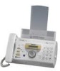
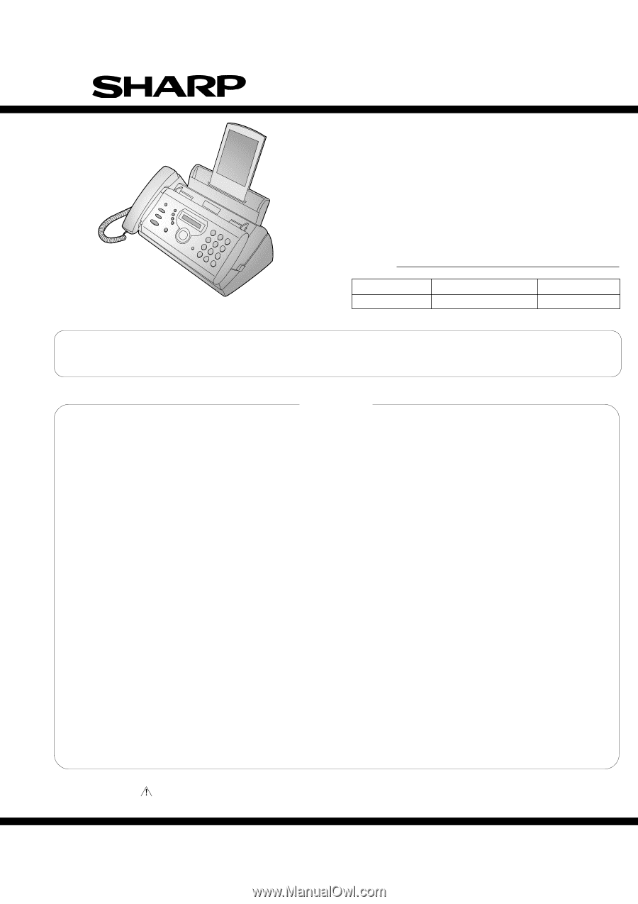
FACSIMILE
UX-A260
Parts marked with "
" are important for maintaining the safety of the set. Be sure to replace these parts with specified ones for
maintaining the safety and performance of the set.
This document has been published to be used
for after sales service only.
The contents are subject to change without notice.
SHARP CORPORATION
SERVICE MANUAL
MODEL
MODEL
SELECTION CODE
DESTINATION
UX-A260
U
U.S.A.
Chapters 1, 2, 3, 7 and 8 of this manual are omitted because they are partly common to the UX-P100U.
Please refer to previous service manual (00ZUXP100USME) for these chapters.
Illustration: UX-A260U