Sharp CD-DK890N CD-DK890N Operation Manual - Page 8
Control, and indicator, continued
 |
View all Sharp CD-DK890N manuals
Add to My Manuals
Save this manual to your list of manuals |
Page 8 highlights
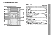
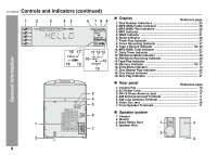
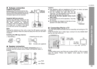
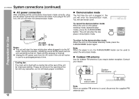
CD-DK890N Controls and indicators (continued) 12 3 45 6 789 General Information 16 17 11 12 13 10 14 18 19 15 3 4 5 6 1 7 AC INPUT 2 Display Reference page 1. Disc Number Indicators 23 2. MP3/WMA Folder Indicator 26 3. MP3/WMA Title Indicators 26 4. MP3 Indicator 21 5. WMA Indicator 21 6. Sleep Indicator 38 7. Timer Play Indicator 37 8. Timer Recording Indicator 37 9. Tape 2 Record Indicator 34, 35 10. MP3/WMA Total Indicator 27 11. Daily Timer Indicator 37 12. FM Stereo Mode Indicator 30 13. FM Stereo Receiving Indicator 30 14.Tape Play Indicator 32 15. Memory Indicator 25, 31 16. Extra Bass Indicator 14 17. Disc Repeat Play Indicator 24 18. Disc Pause Indicator 22 19. Disc Play Indicator 21 Rear panel Reference page 1. Cooling Fan 12 2. AC Power Cord 12 3. FM 75 Ohms Antenna Jack 11 4. AM Antenna Ground Terminal 11 5. AM Loop Antenna Terminal 11 6. Video Out Jack 39 7. Front Speaker Terminals 11 Speaker system 1. Tweeter 2. Woofer 3. Bass Reflex Duct 1 3 4. Speaker Wire 2 4 8
-
 1
1 -
2
-
 3
3 -
 4
4 -
 5
5 -
 6
6 -
 7
7 -
 8
8 -
 9
9 -
 10
10 -
 11
11 -
 12
12 -
 13
13 -
14
-
15
-
16
-
17
-
18
-
19
-
20
-
21
-
22
-
23
-
24
-
25
-
26
-
27
-
28
-
29
-
30
-
31
-
32
-
33
-
34
-
35
-
36
-
37
-
38
-
39
-
40
-
41
-
42
-
43
-
44
 |
 |
