Sharp CD-E500 Service Manual - Page 48
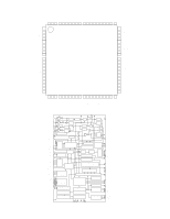
IC701 RH-iX0058SJZZ: System Microcomputer IX0058SJ 1/2
 |
View all Sharp CD-E500 manuals
Add to My Manuals
Save this manual to your list of manuals |
Page 48 highlights
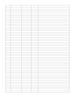
CD-E500 CD-E55/E44 IC701 RH-iX0058SJZZ: System Microcomputer (IX0058SJ) (1/2) Pin No. Port Name Terminal Name Input/Output Function 1 P16 TIMER_LED Output Timer LED control. 2* P17 RDS_DATA Input/Output Open 3* P30 RDS_CLE Input/Output Open 4 P31 CD_CE Output CD DSP CE output. 5 P32 CD_RES Output CD DSP reset. 6 P33 CD_DRF Input CD DRF level detection. 7 P34 CD_WRQ Input CD write read request. 8* P35 PROG0 Input/Output Open 9* P36 PROG1 Input/Output Open 10* P37 PROG2 Input/Output Open 11 RES RESET IN PUT Input Reset signal input. 12* XT1 XT1 Input Open 13* XT2 XT2 Input/Output Open 14 VSS1 GND - Ground voltage. 15 CF1 CF1 Input Main clock. 16 CF2 CF2 Output Main clock. 17 VDD1 VDD1 - (+) Power supply. 18 P80 KEY1_IN Input Key input. 19 P81 KEY2_IN Input Key input. 20* P82 NO USE Input/Output Open 21 P83 FAN_PRT Input Fan protect circuit input. 22 P84 MODE_CKECK Input Ground level input. 23 P85 T2_TAPE2_SW Input Tape SW detection. 24* P86 T1_TAPE1_SW Input/Output Open 25* P87 RDS_VSM Input/Output Open 26 P70 SYS_STOP Input System stop input. 27 P71 X-BASS/DEMO Input Key input. 28 P72 POWER_KEY Input Key input. 29 P73 IRQ Input Remocon input. 30-38 S0/T0-S8/T8 G9-G1 Output FL(VFD) segment driver. 39*-45* S9/T9-S15/T15 NO USE Input/Output Open 46 VDD3 VDD3 - (+) Power supply. 47-50 S16-S19 P1-P4 Output FL(VFD) segment driver. 51 FIX0 GND - Connect to GND. 52-67 S20-S35 P5-P20 Output FL(VFD) segment driver. 68 S36 DISC_NO_SW Input Tray disc no. SW detection. 69 S37 DISC1_SW Input Tray disc 1 SW detection. 70 S38 DISC_UP_SW Input Tray disc up SW detection. 71 S39 CLOSE_SW Input Tray close SW detection. 72 VDD4 VDD4 - (+) Power supply. 73 S40 ROTATE Output Tray motor control. 74 S41 DISC_DOWN_SW Input Tray disc down SW detection. 75 S42 OPEN_SW Input Tray open SW detection. 76 S43 TAPE_BIAS Output Tape record bias. 77 S44 REC_PLAY Output Tape REC/PLAY change. 78 S45 REC Input Tape 2 rec SW detection. 79 S46 MOTOR Output Tape motor control. 80 S47 T1_SOL Output Tape 1 solenoid control. 81 S48 T2_SOL Output Tape 2 solenoid control. 82 S49 T1_RUN_PLUS Input Tape 1 RUN PULSE input. 83 S50 T2_RUN_PLUS Input Tape 2 RUN PULSE input. In this unit, the terminal with asterisk mark (*) is (open) terminal which is not connected to the outside. - 48 -
-
 1
1 -
2
-
3
-
4
-
5
-
6
-
7
-
8
-
9
-
10
-
11
-
12
-
13
-
14
-
15
-
16
-
17
-
18
-
19
-
20
-
21
-
22
-
23
-
24
-
25
-
26
-
27
-
28
-
29
-
30
-
31
-
32
-
33
-
34
-
35
-
36
-
37
-
38
-
39
-
40
-
41
-
42
-
 43
43 -
 44
44 -
 45
45 -
 46
46 -
 47
47 -
 48
48 -
 49
49 -
 50
50 -
 51
51 -
 52
52 -
 53
53 -
54
-
55
-
56
-
57
-
58
-
59
-
60
 |
 |