Sharp CD-E500 Service Manual - Page 58
Cabinet Exploded View
 |
View all Sharp CD-E500 manuals
Add to My Manuals
Save this manual to your list of manuals |
Page 58 highlights
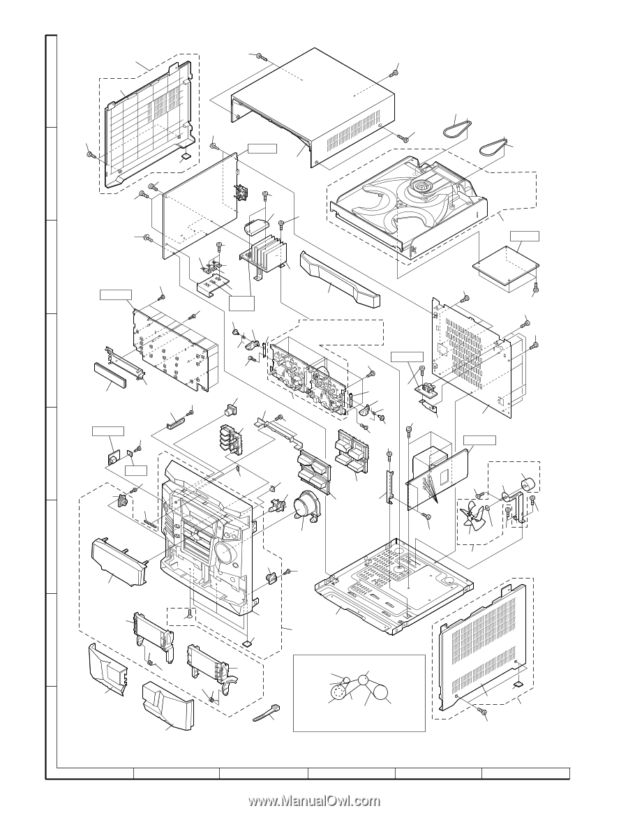
CD-E500 CD-E55/E44 202 615x2 608 A 202-1 234 608x2 602x2 PWB-A 615x2 233 202-2 B 607x2 606x2 205 612x2 IC101 606x2 238-1, 238-2, 238-3, 238-4, 238-5, 238-6 238 602 611x3 IC203 PWB-C C IC201 IC202 235 610x13 PWB-B2 236 Silicon 206 613 Grease 601 229 221 219-1, 219-2, 219-3, 219-4, 219-5, 219-6, 219-7, 219-8, 219-9, 219-10, 219-11 614x4 611x4 608x4 614x4 D 231 611x8 PWB-B4 605 VFD701 227 610 220 PWB-B3 610 213 228 218 219 610x2 222 606 230 232 601 603x4 223 605 606 211 PWB-B1 E 201-2 PWB 610 212 210 209 216 214 215 224 204-4 (M101) 604x2 204-1 237x6 606 217 606x2 204-2 606 204-3 F 204 201-2 610 201-5 201-3 609x3 G 201-1 201-8x2 201 225 BELT CONNECTION 201-6 201-4 FF/REW ROLLER ASS'Y Tape Motor 219-10(M801) 201-7 219-1 207 FLYWHEEL 219-3 219-2 FLYWHEEL ASS'Y MAIN BELT ASS'Y 226 TAPE2 TAPE1 H 208 203-2 203-1 203 608x2 Note: Only the unit and consumable parts are supplied as parts supply for the Tape mechanism. 1 2 3 4 5 6 Figure 7 CABINET EXPLODED VIEW - 7 -
-
 1
1 -
2
-
3
-
4
-
5
-
6
-
7
-
8
-
9
-
10
-
11
-
12
-
13
-
14
-
15
-
16
-
17
-
18
-
19
-
20
-
21
-
22
-
23
-
24
-
25
-
26
-
27
-
28
-
29
-
30
-
31
-
32
-
33
-
34
-
35
-
36
-
37
-
38
-
39
-
40
-
41
-
42
-
43
-
44
-
45
-
46
-
47
-
48
-
49
-
50
-
51
-
52
-
 53
53 -
 54
54 -
 55
55 -
 56
56 -
 57
57 -
 58
58 -
 59
59 -
 60
60
 |
 |