Sharp CD-E500 Service Manual - Page 7
Removing And Reinstalling The Main Parts - pc -
 |
View all Sharp CD-E500 manuals
Add to My Manuals
Save this manual to your list of manuals |
Page 7 highlights
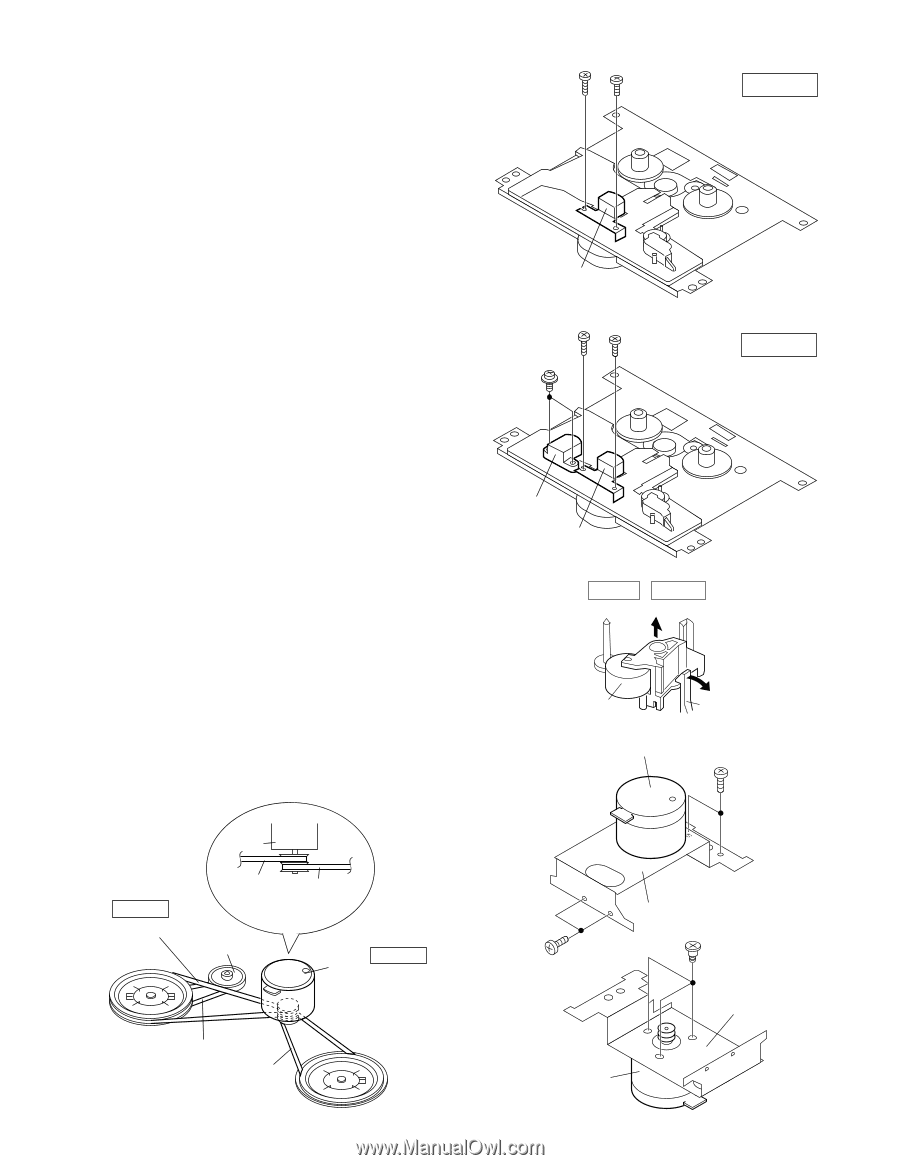
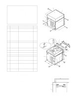
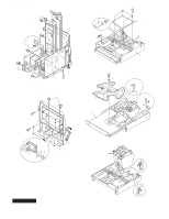
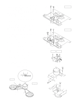
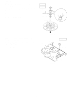
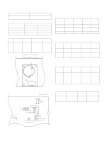
REMOVING AND REINSTALLING THE MAIN PARTS TAPE MECHANISM SECTION Perform steps 1 to 6 and 8 of the disassembly method to remove the tape mechanism. (A1)x1 ø2x7mm (A1)x1 ø2x3mm How to remove the record/playback and erase heads (TAPE 1) (See Fig. 7-1) 1. When you remove the screws (A1) x 2 pcs., the record/ playback head can be removed. How to remove the playback head (TAPE 2) (See Fig. 7-2) 1. When you remove the screws (B1) x 2 pcs., the erase head can be removed. 2. When you remove the screws (B2) x 2 pcs., the record/ playback head can be removed. Note: After replacing the heads and performing the azimuth adjustment, be sure to apply screwlock. Record/ Playback Head Figure 7-1 (B2)x1 ø2x7mm (B2)x1 ø2x3mm How to remove the pinch roller (TAPE 1,2) (See Fig. 7-3) 1. When you remove the screw (C1) x 1 pc., the pinch roller can be removed. Note: When installing the pinch roller, pay attention to the spring mounting position. How to remove the motor (See Fig. 7-4) 1. Remove the belt. 2. Remove the screws (D1) x 4 pcs., to remove the motor bracket. 3. Remove the screws (D2) x 3 pcs., to remove the motor. (B1)x2 ø2x8mm Erase Head Record/ Playback Head Figure 7-2 TAPE 1 TAPE 2 CD-E500 CD-E55/E44 TAPE 1 TAPE 2 How to remove the belt (TAPE 1) (See Fig. 7-5) 1. Remove the main belt (F1) x 1 pc., from the motor side. How to remove the belt (TAPE 2) (See Fig. 7-5) 1. Remove the main belt (G1) x 1 pc., from the motor side. 2. Remove the FF/REW belt (G2) x 1 pc. Pinch Roller (C1)x1 Figure 7-3 Motor Pinch Roller Pawl (D1)x2 ø2x4mm TAPE 2 Main Belt (G1)x1 Motor TAPE 2 Main Belt (G1)x1 REW/FF Clutch Ass'y TAPE 1 Main Belt (F1)x1 TAPE 1 Motor REW/FF Belt (G2)x1 Main Belt (F1)x1 Figure 7-5 - 7 - (D1)x2 ø2x4mm Motor Bracket (D1)x3 Special Screw Motor Bracket Motor Figure 7-4
-
 1
1 -
 2
2 -
 3
3 -
 4
4 -
 5
5 -
 6
6 -
 7
7 -
 8
8 -
 9
9 -
 10
10 -
 11
11 -
 12
12 -
13
-
14
-
15
-
16
-
17
-
18
-
19
-
20
-
21
-
22
-
23
-
24
-
25
-
26
-
27
-
28
-
29
-
30
-
31
-
32
-
33
-
34
-
35
-
36
-
37
-
38
-
39
-
40
-
41
-
42
-
43
-
44
-
45
-
46
-
47
-
48
-
49
-
50
-
51
-
52
-
53
-
54
-
55
-
56
-
57
-
58
-
59
-
60
 |
 |