Sharp CD-E500 Service Manual - Page 5

Disassembly - service manual

Page 5 highlights

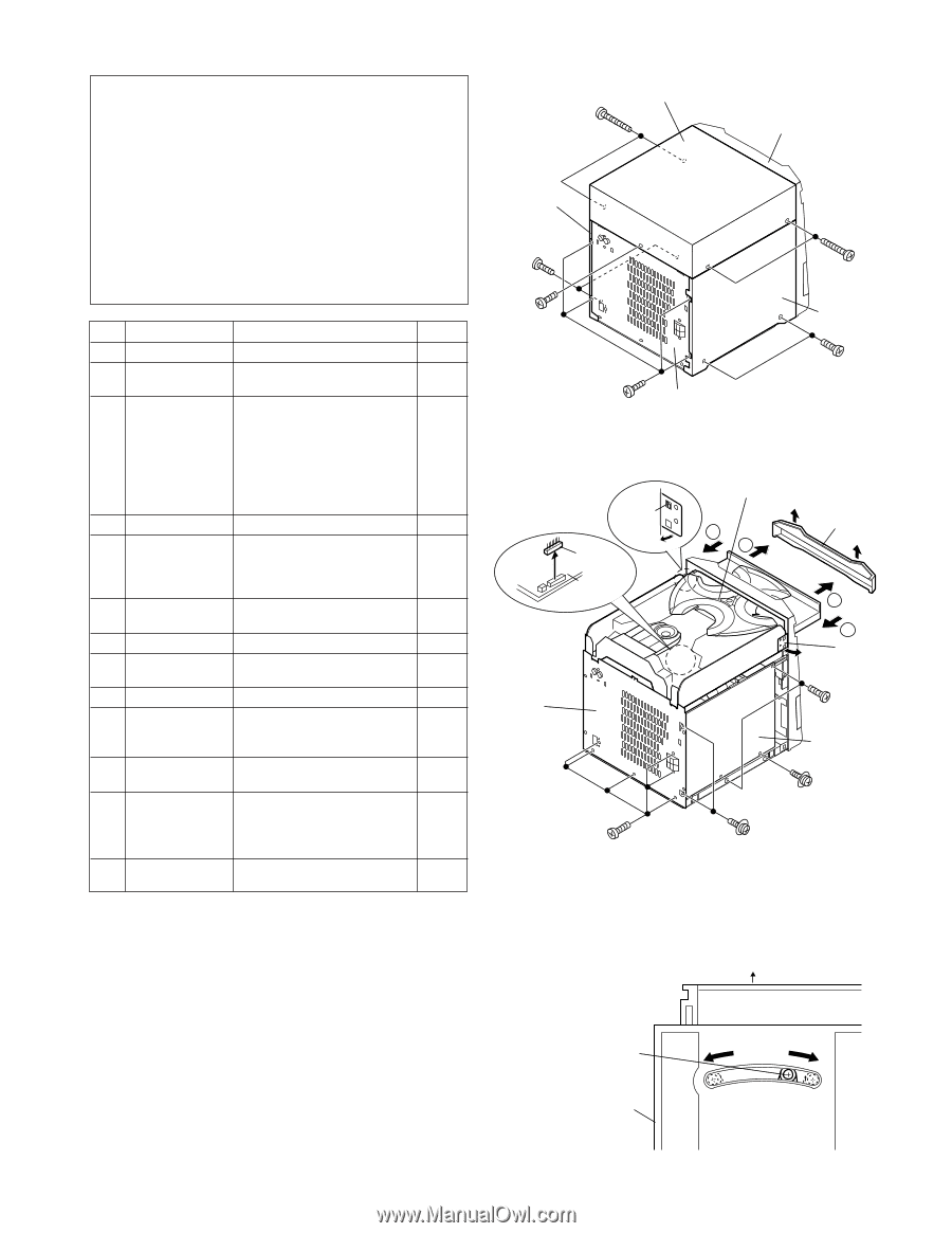
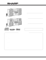
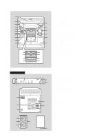
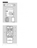
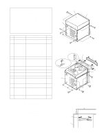
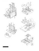
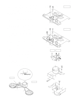
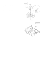
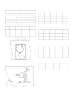
DISASSEMBLY CD-E500 CD-E55/E44 Caution on Disassembly Follow the below-mentioned notes when disassembling the unit and reassembling it, to keep it safe and ensure excellent performance: 1. Take cassette tape and compact disc out of the unit. 2. Be sure to remove the power supply plug from the wall outlet before starting to disassemble the unit. 3. Take off nylon bands or wire holders where they need to be removed when disassembling the unit. After servicing the unit, be sure to rearrange the leads where they were before disassembling. 4. Take sufficient care on static electricity of integrated circuits and other circuits when servicing. STEP REMOVAL PROCEDURE FIGURE 1 Top Cabinet 1. Screw A1) x5 5-1 2 Side Panel (Left/Right) 1. Screw B1) x8 5-1 3 CD Player Unit 1. Turn on the power supply, .. 5-2 open the disc tray, take out the CD tray cover, and close. Note 1) 2. CD Tray Cover ........ (C1) x1 3. Hook C2) x2 4. Socket C3) x1 5. Socket C4) x2 6-1 4 Rear Panel 1. Screw D1) x8 5-2 5 Main PWB 1. Screw E1) x3 5-2 2. Screw E2) x2 6-1 3. Socket E3) x9 4. Socket E4) x2 6-2 6 Front Panel 1. Screw F1) x3 6-1 2. Hook F2) x2 7 Display PWB 1. Screw G1) x13 6-2 8 Tape Mechanism 1. Open the cassette holder. 6-2 2. Screw H1) x8 9 Headphones PWB 1. Screw J1) x1 6-2 10 CD Servo PWB 1. Screw K1) x4 6-3 (Note 2) 2. Socket K2) x2 3. Solder K3) x2 11 Turntable 1. Screw L1) x1 6-4 2. Spacer L2) x1 12 Loading Tray 1. Push forward the loading tray. 6-4 2. Inserting the flat head into the hole, push in the direction indicated by the arrow. ... (M1) x2 13 CD Mechanism 1. Hook N1) x2 6-5 Block Note 1: How to open the changer manually. (Fig. 5-3) 1. In this state, turn fully the loading Gear in the arrow direction through the hold on the loading tray bottom. 2. After that,push foward the loading tray. Note 2: 1. After removing the connector for the optical pickup from the connector, wrap the conductive aluminium foil around the front end of the connector so as to protect the optical pickup from electrostatic damage. Top Cabinet (A1)x2 ø3x16mm Front Panel Side Panel (Right) (B1)x2 ø3x8mm (A1)x1 ø3x8mm (B1)x4 ø3x10mm Rear Panel Figure 5-1 (A1)x2 ø3x16mm Side Panel (Left) (B1)x2 ø3x8mm (C2)x1 Pull (C3)x1 CD Servo PWB Rear Panel CD Player Unit CD Tray Cover (C1)x1 2 1 1 2 (C2)x1 Pull (E1)x2 ø3x6mm Main PWB (D1)x6 ø3x8mm (D1)x2 ø3x10mm (E1)x1 ø3x10mm Figure 5-2 Front Side Loading Gear or CD Player Unit (Bottom View) - 5 - Figure 5-3

  • 1
  • 2
  • 3
  • 4
  • 5
  • 6
  • 7
  • 8
  • 9
  • 10
  • 11
  • 12
  • 13
  • 14
  • 15
  • 16
  • 17
  • 18
  • 19
  • 20
  • 21
  • 22
  • 23
  • 24
  • 25
  • 26
  • 27
  • 28
  • 29
  • 30
  • 31
  • 32
  • 33
  • 34
  • 35
  • 36
  • 37
  • 38
  • 39
  • 40
  • 41
  • 42
  • 43
  • 44
  • 45
  • 46
  • 47
  • 48
  • 49
  • 50
  • 51
  • 52
  • 53
  • 54
  • 55
  • 56
  • 57
  • 58
  • 59
  • 60

– 5 –
CD-E500
CD-E55/E44
DISASSEMBLY
Caution on Disassembly
Follow the below-mentioned notes when disassembling
the unit and reassembling it, to keep it safe and ensure
excellent performance:
1. Take cassette tape and compact disc out of the unit.
2. Be sure to remove the power supply plug from the wall
outlet before starting to disassemble the unit.
3. Take off nylon bands or wire holders where they need to
be removed when disassembling the unit. After servicing
the unit, be sure to rearrange the leads where they were
before disassembling.
4. Take sufficient care on static electricity of integrated
circuits and other circuits when servicing.
Figure 5-2
Figure 5-1
Figure 5-3
Note 1:
How to open the changer manually. (Fig. 5-3)
1. In this state, turn fully the loading Gear in the arrow direction
through the hold on the loading tray bottom.
2. After that,push foward the loading tray.
1
Top Cabinet
1. Screw
......................
(A1) x5
5-1
2
Side Panel
1. Screw
......................
(B1) x8
5-1
(Left/Right)
3
CD Player Unit
1. Turn on the power supply, ..
5-2
open the disc tray, take out
the CD tray cover, and close.
..................................
(Note 1)
2. CD Tray Cover
........
(C1) x1
3. Hook
........................
(C2) x2
4. Socket
.....................
(C3) x1
5. Socket
.....................
(C4) x2
6-1
4
Rear Panel
1. Screw
......................
(D1) x8
5-2
5
Main PWB
1. Screw
......................
(E1) x3
5-2
2. Screw
......................
(E2) x2
6-1
3. Socket
.....................
(E3) x9
4. Socket
.....................
(E4) x2
6-2
6
Front Panel
1. Screw
.......................
(F1) x3
6-1
2. Hook
.........................
(F2) x2
7
Display PWB
1. Screw
....................
(G1) x13
6-2
8
Tape Mechanism
1. Open the cassette holder.
6-2
2. Screw
......................
(H1) x8
9
Headphones PWB
1. Screw
.......................
(J1) x1
6-2
10
CD Servo PWB
1. Screw
......................
(K1) x4
6-3
(Note 2)
2. Socket
.....................
(K2) x2
3. Solder
......................
(K3) x2
11
Turntable
1. Screw
.......................
(L1) x1
6-4
2. Spacer
......................
(L2) x1
12
Loading Tray
1.
Push forward the loading tray.
6-4
2.
Inserting the flat head into the
hole, push in the direction indi-
cated by the arrow
. ...
(M1) x2
13
CD Mechanism
1. Hook
........................
(N1) x2
6-5
Block
STEP
REMOVAL
PROCEDURE
FIGURE
Side Panel
(Right)
Side Panel
(Left)
Top Cabinet
Front
Panel
(A1)x2
ø3x16mm
(A1)x2
ø3x16mm
(B1)x2
ø3x8mm
(B1)x2
ø3x8mm
(B1)x4
ø3x10mm
(A1)x1
ø3x8mm
Rear Panel
1
1
2
2
(D1)x6
ø3x8mm
(D1)x2
ø3x10mm
(E1)x2
ø3x6mm
CD Player Unit
Rear
Panel
Main
PWB
CD Tray Cover
(E1)x1
ø3x10mm
(C2)x1
(C3)x1
CD Servo
PWB
(C1)x1
Pull
(C2)x1
Pull
CD Player Unit
(Bottom View)
Loading Gear
Front Side
or
Note 2:
1. After removing the connector for the optical pickup from the
connector, wrap the conductive aluminium foil around the front end
of the connector so as to protect the optical pickup from electro-
static damage.