Sharp CD-E500 Service Manual - Page 8
TAPE 1, TAPE 2, Washer, Driver, Stop Washer, Mechanism, Chassis, Washerx2, Flywheel
 |
View all Sharp CD-E500 manuals
Add to My Manuals
Save this manual to your list of manuals |
Page 8 highlights
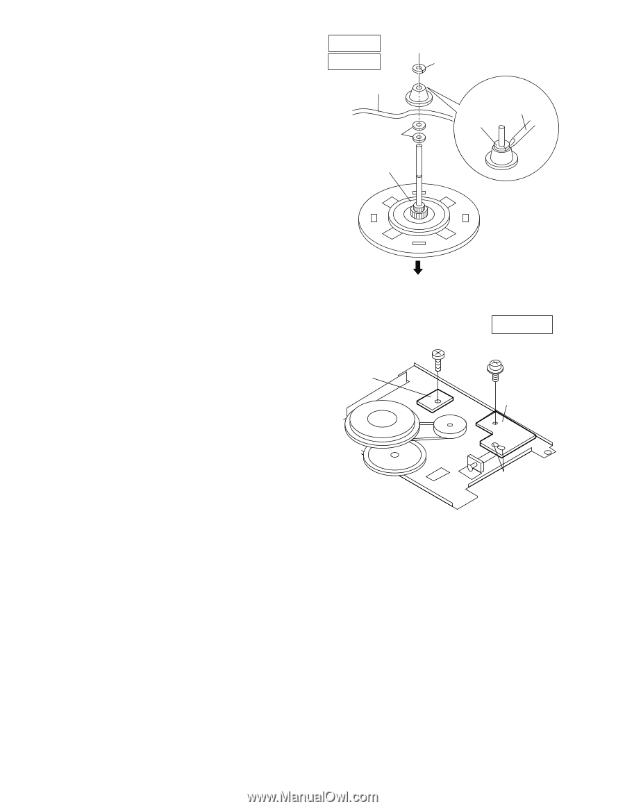
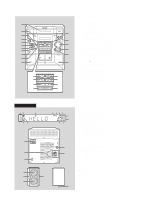
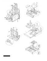
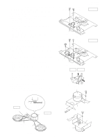
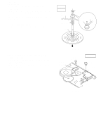
CD-E500 CD-E55/E44 How to remove the flywheel (TAPE 1,2) (See Fig. 8-1.) 1. Remove the stop washer (H1) x 1 pc., with a small precision screwdriver to extract the flywheel from the capstan metal. Note: When the stop washer is deformed or damaged, replace it with a new one. How to reinstall the parts Install each part in the reverse order of the removal with care. TAPE 1 TAPE 2 Mechanism Chassis Washerx2 Flywheel (H1)x1 Stop Washer Stop Driver Washer How to remove the tape mechanism PWB (TAPE 1,2) (See Fig. 8-2.) 1. Remove the screw (J1) x 1 pc., to remove the tape mechanism PWB. 2. Remove the screw (J2) x 1 pc. 3. Remove the solder joints (J3) x 2 pcs., to remove the tape mechanism PWB. Figure 8-1 Tape Mechanism PWB (J1)x1 ø2x3mm TAPE 1,2 (J2)x1 ø2x8mm Tape Mechanism PWB Figure 8-2 (J3)x2 Solder Joint - 8 -
-
 1
1 -
2
-
 3
3 -
 4
4 -
 5
5 -
 6
6 -
 7
7 -
 8
8 -
 9
9 -
 10
10 -
 11
11 -
 12
12 -
 13
13 -
14
-
15
-
16
-
17
-
18
-
19
-
20
-
21
-
22
-
23
-
24
-
25
-
26
-
27
-
28
-
29
-
30
-
31
-
32
-
33
-
34
-
35
-
36
-
37
-
38
-
39
-
40
-
41
-
42
-
43
-
44
-
45
-
46
-
47
-
48
-
49
-
50
-
51
-
52
-
53
-
54
-
55
-
56
-
57
-
58
-
59
-
60
 |
 |