Sharp XL-UH260 Service Manual - Page 1
Sharp XL-UH260 Manual
 |
View all Sharp XL-UH260 manuals
Add to My Manuals
Save this manual to your list of manuals |
Page 1 highlights
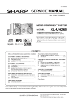
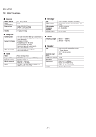
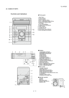
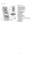
XL-UH260 SERVICE MANUAL No. S2603XLUH260/ MICRO COMPONENT SYSTEM MODEL XL-UH260 XL-UH260 Micro Component System consisting of XL-UH260 (main unit) and CP-UH260 (speaker system). • In the interests of user-safety (Required by safety regulations in some countries) the set should be restored to its original condition and only parts identical to those specified be used. CONTENTS PRECAUTIONS FOR USING LEAD-FREE SOLDER CHAPTER 1. GENERAL DESCRIPTION [1] IMPORTANT SERVICE NOTES 1-1 [2] SPECIFICATIONS 1-2 [3] NAMES OF PARTS 1-3 CHAPTER 2. ADJUSTMENTS [1] CD Section 2-1 [2] TEST MODE 2-2 [3] Standard Specification of Stereo System Error Message Display Contents 2-4 [4] CD Changer Mechanism Section 2-5 CHAPTER 5. CIRCUIT DESCRIPTION [1] WAVEFORMS OF SERVO CIRCUIT 5-1 [2] VOLTAGE 5-3 CHAPTER 6. CIRCUIT SCHEMATICS AND PARTS LAYOUT [1] NOTES ON SCHEMATIC DIAGRAM 6-1 [2] TYPES OF TRANSISTOR AND LED 6-1 [3] WIRING SIDE OF PWB/SCHEMATIC DIAGRAM 6-2 CHAPTER 7. FLOWCHART [1] TROUBLESHOOTING 7-1 CHAPTER 3. MECHANICAL DESCRIPTION [1] REMOVING AND REINSTALLING THE MAIN PARTS 3-1 [2] DISASSEMBLY 3-3 CHAPTER 4. DIAGRAMS [1] BLOCK DIAGRAM 4-1 CHAPTER 8. OTHERS [1] FUNCTION TABLE OF IC 8-1 [2] FL DISPLAY 8-10 Parts Guide Parts marked with " " are important for maintaining the safety of the set. Be sure to replace these parts with specified ones for maintaining the safety and performance of the set. - 1 This document has been published to be used for after sales service only. The contents are subject to change without notice.
-
 1
1 -
 2
2 -
 3
3 -
 4
4 -
 5
5 -
 6
6 -
 7
7 -
8
-
9
-
10
-
11
-
12
-
13
-
14
-
15
-
16
-
17
-
18
-
19
-
20
-
21
-
22
-
23
-
24
-
25
-
26
-
27
-
28
-
29
-
30
-
31
-
32
-
33
-
34
-
35
-
36
-
37
-
38
-
39
-
40
-
41
-
42
-
43
-
44
-
45
-
46
-
47
-
48
-
49
-
50
-
51
-
52
-
53
-
54
-
55
-
56
-
57
-
58
-
59
-
60
-
61
-
62
-
63
-
64
-
65
-
66
-
67
-
68
-
69
-
70
-
71
-
72
-
73
-
74
-
75
-
76
-
77
-
78
-
79
-
80
-
81
-
82
-
83
-
84
-
85
-
86
-
87
-
88
-
89
-
90
-
91
-
92
-
93
-
94
-
95
-
96
-
97
-
98
-
99
-
100
-
101
-
102
-
103
-
104
-
105
-
106
-
107
-
108
-
109
-
110
-
111
-
112
-
113
-
114
-
115
-
116
-
117
-
118
-
119
-
120
-
121
-
122
-
123
-
124
 |
 |