Sharp XL-UH260 Service Manual - Page 45
] Disassembly
 |
View all Sharp XL-UH260 manuals
Add to My Manuals
Save this manual to your list of manuals |
Page 45 highlights
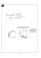
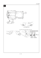
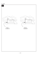
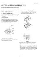
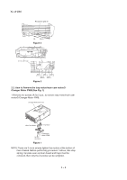
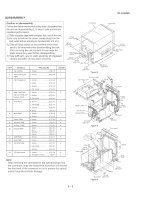
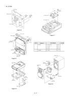
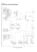
[2] DISASSEMBLY XL-UH260 Caution on disassembly Follow the below-mentioned notes when disassembling the unit and reassembling it, to keep it safe and ensure excellent performance: 1) Take cassette tape and compact disc out of the unit. 2) Be sure to remove the power supply plug from the wall outlet before starting to disassemble the unit. 3) Take off nylon bands or wire holders where they need to be removed when disassembling the unit. After servicing the unit, be sure to rearrange the leads where they were before disassembling. 4) Take sufficient care on static electricity of integrated circuits and other circuits when servicing. Top Cabinet (A1)x2 3x12mm (B1)x2 3x10mm Side Panel (Right) (A1)x2 3x12mm (B1)x2 3x10mm Rear Panel STEP REMOVAL 1 Top Cabinet 2 Side Panel (Left/ Right) 3 CD Changer unit PROCEDURE 1. Screw A1) X 6 2. Screw B1) X 8 FIGURE 1 1 1. Screw C1) X 2 2 (B1)x2 3x10mm Figure 1 CD Servo PWB CD Changer Unit Front Panel (A1)x2 3x12mm Side Panel (Left) (B1)x2 3x10mm (C3)x2 (C4)x2 2. Hook C2) X 2 3. Socket C3) X 2 4. Flat Cable C4) X 2 PULL Front Panel 4 Rear Panel with 1. Screw D1) X 4 2 Speaker PWB and Refresh PWB 2. Socket D2) X 1 3. Flat Cable D3) X 1 5 Front Panel 1. Screw E1) X 2 3 (C1)x1 3x10mm Hook (C2)x1 Hook (C2)x1 PULL 2. Flat Cable E2) X 2 3. Socket E3) X 1 Refresh PWB (C1)x1 3x10mm 6 Main PWB 4. Hook E4) X 2 1. Screw F1) X 4 3 2. Socket F2) X 2 Rear Panel Speaker PWB (D3)x1 7 Power PWB 8 Speaker PWB 9 Refresh PWB 10 Display PWB 11 USB PWB 12 Jack PWB 1. Screw G1) X 4 3 1. Screw H1) X 2 4 1. Screw J1) X 1 4 1. Knob K1) X 1 5 2. Nut K2) X 1 3. Washer K3) X 1 4. Screw K4) X 6 1. Screw L1) X 2 5 1. Screw M1) X 1 5 (D1)x4 3x10mm Figure 2 (E4)x1 PULL (F1)x2 3x6mm (E3)x1 (D2)x1 Front panel 13 CD MP3 PWB 1. Screw N1) X 2 6 2. Flat Cable N2) X 2 3. Socket N3) X 1 14 CD Mechanism 1. Screw P1) X 4 6 2. Changer Chassis..........(P2)X 4 7 Note: After removing the connector for the optical pickup from the connector, wrap the conductive aluminium foil around the front end of the connector so as to protect the optical pickup from electrostatic damage. (F2)x1 (G1)x4 4x6mm Power PWB (E2)x2 Hook (E4)x1 PULL (F2)x1 (E1)x2 3x10mm Main PWB Figure 3 (F1)x2 3x10mm 3 - 3
-
 1
1 -
2
-
3
-
4
-
5
-
6
-
7
-
8
-
9
-
10
-
11
-
12
-
13
-
14
-
15
-
16
-
17
-
18
-
19
-
20
-
21
-
22
-
23
-
24
-
25
-
26
-
27
-
28
-
29
-
30
-
31
-
32
-
33
-
34
-
35
-
36
-
37
-
38
-
39
-
 40
40 -
 41
41 -
 42
42 -
 43
43 -
 44
44 -
 45
45 -
 46
46 -
 47
47 -
 48
48 -
 49
49 -
 50
50 -
51
-
52
-
53
-
54
-
55
-
56
-
57
-
58
-
59
-
60
-
61
-
62
-
63
-
64
-
65
-
66
-
67
-
68
-
69
-
70
-
71
-
72
-
73
-
74
-
75
-
76
-
77
-
78
-
79
-
80
-
81
-
82
-
83
-
84
-
85
-
86
-
87
-
88
-
89
-
90
-
91
-
92
-
93
-
94
-
95
-
96
-
97
-
98
-
99
-
100
-
101
-
102
-
103
-
104
-
105
-
106
-
107
-
108
-
109
-
110
-
111
-
112
-
113
-
114
-
115
-
116
-
117
-
118
-
119
-
120
-
121
-
122
-
123
-
124
 |
 |
