Sharp XL-UH260 Service Manual - Page 57
Circuit Schematics And Parts Layout
 |
View all Sharp XL-UH260 manuals
Add to My Manuals
Save this manual to your list of manuals |
Page 57 highlights
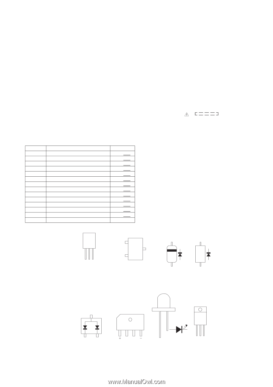
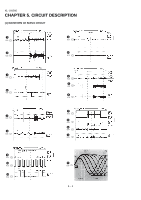
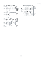
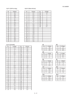
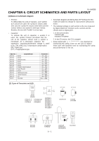
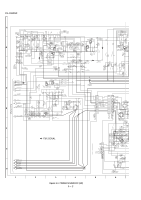
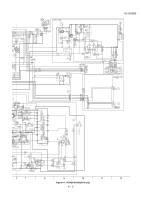
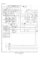
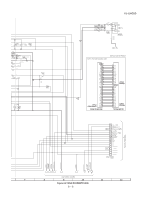
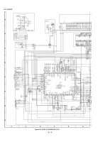
XL-UH260 CHAPTER 6. CIRCUIT SCHEMATICS AND PARTS LAYOUT [1] Notes on schematic diagram • Resistor: To differentiate the units of resistors, such symbol as K and M are used: the symbol K means 1000 ohm and the symbol M means 1000 kohm and the resistor without any symbol is ohm-type resistor. Besides, the one with "Fusible" is a fuse type. • Schematic diagram and Wiring Side of P.W.Board for this model are subject to change for improvement without prior notice. • The indicated voltage in each section is the one measured by Digital Multimeter between such a section and the chassis with no signal given. • Capacitor: To indicate the unit of capacitor, a symbol P is used: this symbol Pmeans pico-farad and the 1. In the tuner section, indicates AM indicates FM stereo unit of the capacitor without such a symbol is 2. In the CD section, the CD is stopped. microfarad. As to electrolytic capacitor, the • Parts marked with " " ( ) are important for expression "capacitance/withstand voltage is used". maintaining the safety of the set. Be sure to replace (CH), (TH), (RH), (UJ): Temperature compensation these parts with specified ones for maintaining the safety (ML): Mylar type and performance of the set. (P.P.): Polypropylene type REF. NO SW701 SW702 SW703 SW704 SW705 SW706 SW707 SW708 SW709 SW710 SW711 SW712 VR701 DESCRIPTION DISC4 DISC5 OPEN/CLOSE DISC1 DISC2 DISC3 POWER ON/STAND-BY PLAY/PAUSE STOP VIDEO/AUX/USB TUNER (BAND) CD VOLUME POSITION ON-OFF ON-OFF ON-OFF ON-OFF ON-OFF ON-OFF ON-OFF ON-OFF ON-OFF ON-OFF ON-OFF ON-OFF MAX -MIN [2 ] Types of Transistor and LED FRONT VIEW ECB (S)(G)(D) (1)(2)(3) KTA1271 Y KTA1274 Y KIA78L05 KTC3199 GR KTC3203 Y KTC3205 Y B (3) TOP C VIEW (2) E (1) KRA102 S KRC107 S KRC102 S KRC104 S KTA1504 Y KTC3875 GR KTC1544 T KTC3265 Y TOP VIEW DS1SS119 TOP VIEW 1N404S 1N4148H TOP VIEW KDS184 KDS160 FRONT VIEW AC AC TS10B05G TS4B05G 6 - 1 FRONT VIEW FRONT VIEW 343VC3F SDPB50CD SDPB40F2A ECB KIA7805A
-
 1
1 -
2
-
3
-
4
-
5
-
6
-
7
-
8
-
9
-
10
-
11
-
12
-
13
-
14
-
15
-
16
-
17
-
18
-
19
-
20
-
21
-
22
-
23
-
24
-
25
-
26
-
27
-
28
-
29
-
30
-
31
-
32
-
33
-
34
-
35
-
36
-
37
-
38
-
39
-
40
-
41
-
42
-
43
-
44
-
45
-
46
-
47
-
48
-
49
-
50
-
51
-
 52
52 -
 53
53 -
 54
54 -
 55
55 -
 56
56 -
 57
57 -
 58
58 -
 59
59 -
 60
60 -
 61
61 -
 62
62 -
63
-
64
-
65
-
66
-
67
-
68
-
69
-
70
-
71
-
72
-
73
-
74
-
75
-
76
-
77
-
78
-
79
-
80
-
81
-
82
-
83
-
84
-
85
-
86
-
87
-
88
-
89
-
90
-
91
-
92
-
93
-
94
-
95
-
96
-
97
-
98
-
99
-
100
-
101
-
102
-
103
-
104
-
105
-
106
-
107
-
108
-
109
-
110
-
111
-
112
-
113
-
114
-
115
-
116
-
117
-
118
-
119
-
120
-
121
-
122
-
123
-
124
 |
 |