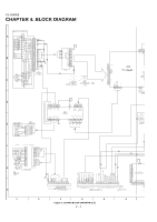
Sharp XL-UH260 Service Manual - Page 44
How to Remove the tray motor/main cam motor/5, Changer Motor PWB See Fig. 1,
 |
View all Sharp XL-UH260 manuals
Add to My Manuals
Save this manual to your list of manuals |
Page 44 highlights
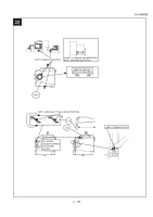
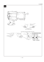
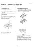
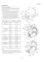
XL-UH260 Reduction gear D Up Down Figure 4 Gear up down board Mark 1 Mark 3 Mark 5 (DISC 1) (DISC 3) (DISC 5) Mark 2 Mark 4 (DISC 2) (DISC 4) Figure 5 2.2. How to Remove the tray motor/main cam motor/5Changer Motor PWB (See Fig. 1) 1.Remove the screws (A1)x 2 pcs., to remove tray motor/main cam motor/5-Changer Motor PWB. Changer Mechanism Unit Main Cam Motor Tray Motor 5-Changer Motor PWB (A1)X2 φ2x10mm Figure 1 NOTE:There are 2 more screws tighten the motors at the bottom of main chassis. Before performing procedure 1 above, disc stop spring, top plate sear up down board and trays must be removed, then only the 2 screws can be untighten. 3 - 2
-
 1
1 -
2
-
3
-
4
-
5
-
6
-
7
-
8
-
9
-
10
-
11
-
12
-
13
-
14
-
15
-
16
-
17
-
18
-
19
-
20
-
21
-
22
-
23
-
24
-
25
-
26
-
27
-
28
-
29
-
30
-
31
-
32
-
33
-
34
-
35
-
36
-
37
-
38
-
 39
39 -
 40
40 -
 41
41 -
 42
42 -
 43
43 -
 44
44 -
 45
45 -
 46
46 -
 47
47 -
 48
48 -
 49
49 -
50
-
51
-
52
-
53
-
54
-
55
-
56
-
57
-
58
-
59
-
60
-
61
-
62
-
63
-
64
-
65
-
66
-
67
-
68
-
69
-
70
-
71
-
72
-
73
-
74
-
75
-
76
-
77
-
78
-
79
-
80
-
81
-
82
-
83
-
84
-
85
-
86
-
87
-
88
-
89
-
90
-
91
-
92
-
93
-
94
-
95
-
96
-
97
-
98
-
99
-
100
-
101
-
102
-
103
-
104
-
105
-
106
-
107
-
108
-
109
-
110
-
111
-
112
-
113
-
114
-
115
-
116
-
117
-
118
-
119
-
120
-
121
-
122
-
123
-
124
 |
 |

XL-UH260
3 – 2
2.2. How to Remove the tray motor/main cam motor/5-
Changer Motor PWB (See Fig. 1)
1.Remove the screws (A1)x 2 pcs., to remove tray motor/main cam
motor/5-Changer Motor PWB.
Figure 1
NOTE:There are 2 more screws tighten the motors at the bottom of
main chassis. Before performing procedure 1 above, disc stop
spring, top plate sear up down board and trays must be
removed, then only the 2 screws can be untighten.
5-Changer
Motor PWB
Tray Motor
Changer Mechanism Unit
Main Cam Motor
(A1)X2
φ
2x10mm
Figure 4
Figure 5
Reduction gear D
Up
Down
Mark 1
(DISC 1)
(DISC 2)
(DISC 3)
(DISC 4)
(DISC 5)
Gear up down board
Mark 3
Mark 5
Mark 2
Mark 4