Sharp XL-UH260 Service Manual - Page 43
Mechanical Description
 |
View all Sharp XL-UH260 manuals
Add to My Manuals
Save this manual to your list of manuals |
Page 43 highlights
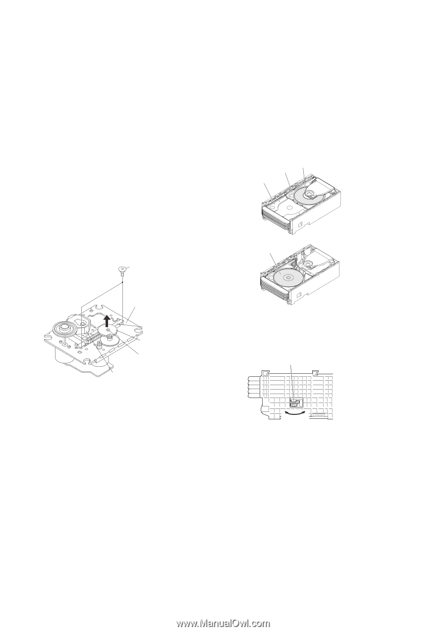
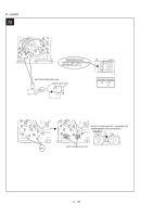
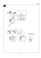
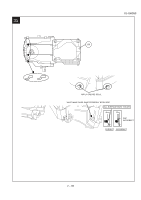
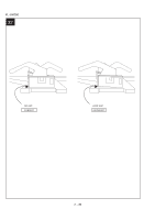
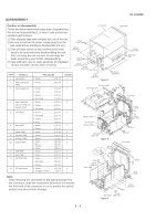
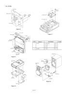
CHAPTER 3. MECHANICAL DESCRIPTION [1] REMOVING AND REINSTALLING THE MAIN PARTS XL-UH260 1. CD MECHANISM SECTION Perform steps 1, 2, 9, 10, 11 and 12 of the disassembly method to remove the CD mechanism. 1.1. Remove the pickup. (See Fig. 1) 1. Remove the stop washer (A1) x 1 pc., to remove the gear (A2) x 1 pc. 2. Remove the screws (A3) x 2 pcs., to remove the shaft (A4) x 1 pc. 3. Remove the pickup. 2.1. How to remove CD Disc (See Fig. 2~5) 1. When CD is at play position (Figure 2), rotate reduction gear C clock-wise as shown in Figure 3 Until disc tray is at stock position, then rotate further to eject the disc tray so that CD can be removed from the tray. CD Disc Disc Tray Guide Tray Note After removing the connector for the optical pickup from the connector wrap the conductive aluminium foil around the front end of connector so as to protect the optical pickup from electrostatic damage. CD At play position. CD Disc (A3)x2 φ2.6x6mm CD Mechanism Shaft (A4)x1 Gear (A2)x1 Stop Washer (A1)x1 Pickup Unit Figure 1 CD At stalk position. Figure 2 Reduction gear C 2. CHANGER MECHANISM SECTION Perform steps 1, 2, 9 and 10 of the disassembly method to remove the CD changer mechanism. Front Rear Figure 3 2. In another case, if CD mechanism is at tray No.1 play position and to remove CD located in tray No.3, the procedure is as follows: If the gear up down board is located at tray No.1 position, then rotate gear clock-wise until it at stock position. Rotate reduction gear D clockwise (Figure 4) to move the CD mechanism to tray No.3 position.This is confirmed by checking the gear up down board position by the marking as indicated on the main chassis as shown in Figure 5. 3 - 1
-
 1
1 -
2
-
3
-
4
-
5
-
6
-
7
-
8
-
9
-
10
-
11
-
12
-
13
-
14
-
15
-
16
-
17
-
18
-
19
-
20
-
21
-
22
-
23
-
24
-
25
-
26
-
27
-
28
-
29
-
30
-
31
-
32
-
33
-
34
-
35
-
36
-
37
-
 38
38 -
 39
39 -
 40
40 -
 41
41 -
 42
42 -
 43
43 -
 44
44 -
 45
45 -
 46
46 -
 47
47 -
 48
48 -
49
-
50
-
51
-
52
-
53
-
54
-
55
-
56
-
57
-
58
-
59
-
60
-
61
-
62
-
63
-
64
-
65
-
66
-
67
-
68
-
69
-
70
-
71
-
72
-
73
-
74
-
75
-
76
-
77
-
78
-
79
-
80
-
81
-
82
-
83
-
84
-
85
-
86
-
87
-
88
-
89
-
90
-
91
-
92
-
93
-
94
-
95
-
96
-
97
-
98
-
99
-
100
-
101
-
102
-
103
-
104
-
105
-
106
-
107
-
108
-
109
-
110
-
111
-
112
-
113
-
114
-
115
-
116
-
117
-
118
-
119
-
120
-
121
-
122
-
123
-
124
 |
 |