Snapper 200Z Operater's Manual - Page 25
Cutting Height Adjustment - deck
 |
View all Snapper 200Z manuals
Add to My Manuals
Save this manual to your list of manuals |
Page 25 highlights
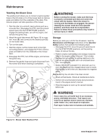
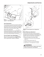
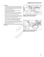
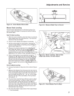
Adjustments and Service Installation 1. Disengage the PTO, engage the parking brake, lock the ground speed levers into their START/PARK posi- A tions, turn off the ignition, remove the key, and wait for all moving parts to stop. 2. Lower the mower deck to its lowest position (see C Cutting Height Adjustment). B 3. Pivot the front wheels out of the way and slide the mower deck under the unit. Place a 2 x 4 or similar support under each end of the mower deck. 4. Insert the front lift rods (C, Figure 18) into the bottom holes in the front mower deck bracket (B), and secure each with a washer and hairpin clip (A). Figure 17. Rear Deck Lift Components (Right side shown, left side same) 5. Insert the rear lift arms (C, Figure 17) into the front holes in the rear mower deck brackets (B), and secure each with a washer and hairpin clip (A). 6. Pull back on the tensioning idler (D, Figure 16) in the direction indicated, and install the belt onto the PTO pulley as shown in Figure 16. r n Important: Be sure the belt is installed properly onto all pulleys. t fo ctioC A B o u Figure 18. Front Deck Lift Components RNeprodRight side shown, left side same) 25
-
 1
1 -
2
-
3
-
4
-
5
-
6
-
7
-
8
-
9
-
10
-
11
-
12
-
13
-
14
-
15
-
16
-
17
-
18
-
19
-
 20
20 -
 21
21 -
 22
22 -
 23
23 -
 24
24 -
 25
25 -
 26
26 -
 27
27 -
 28
28 -
 29
29 -
 30
30 -
31
-
32
-
33
-
34
-
35
-
36
-
37
-
38
-
39
-
40
-
41
-
42
-
43
-
44
-
45
-
46
-
47
-
48
-
49
-
50
-
51
-
52
-
53
-
54
-
55
-
56
-
57
-
58
-
59
-
60
-
61
-
62
-
63
-
64
-
65
-
66
-
67
-
68
-
69
-
70
-
71
-
72
 |
 |
