Sony KP-53HS10 Operating Instructions - Page 14
Connecting a VCR and Projection TV to a Cable Box, AUDIO and S VIDEO OUT on the VCR - rear projection tv
 |
View all Sony KP-53HS10 manuals
Add to My Manuals
Save this manual to your list of manuals |
Page 14 highlights
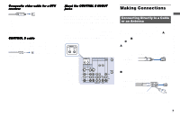
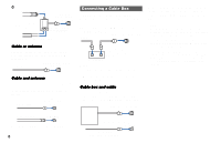
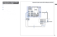
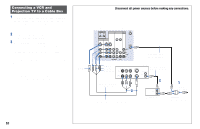
Connecting a VCR and Projection TV to a Cable Box 1 Connect the single (input) jack of the splitter to the incoming cable connection, and connect the other two (output) jacks (using the coaxial cable) to IN on the cable box and VHF/UHF on the projection TV. 2 Using a coaxial cable, connect OUT on the cable box to IN on the VCR. 3 Using AUDIO and S VIDEO* cables, connect AUDIO and S VIDEO OUT on the VCR to AUDIO and S VIDEO IN on the projection TV (White-AUDIO Left, Red-AUDIO Right). * If your VCR is not equipped with S VIDEO, use a VIDEO cable (yellow) instead of the S VIDEO cable. Note: • To view scrambled channels through the cable box, select the video input which the cable box is connected to by pressing TV/VIDEO. S VIDEO Disconnect all power sources before making any connections. (Rear of projection TV) CONTROL S IN OUT AUX IN OUT VIDEO 4 VIDEO 5 (DTV) SELECT IN VIDEO 1 VIDEO 3 HD VD S VIDEO VIDEO L (MONO) AUDIO R Y Y/G L PB PB/B (MONO) PR PR/R R COMPONENT AUDIO VHF/UHF VIDEO L AUDIO R Coaxial cable (not supplied) VIDEO AUDIO-L AUDIO-R AUDIO R AUDIO L VIDEO LINE IN LINE OUT VMC-810S/820S (not supplied) S VIDEO VCR Coaxial cable (not supplied) VHF/UHF OUT IN 2 3 OUT IN Cable box YC-15V/30V (not supplied) 1 Cable/ Antenna Splitter (not supplied) 10
-
 1
1 -
2
-
3
-
4
-
5
-
6
-
7
-
8
-
 9
9 -
 10
10 -
 11
11 -
 12
12 -
 13
13 -
 14
14 -
 15
15 -
 16
16 -
 17
17 -
 18
18 -
 19
19 -
20
-
21
-
22
-
23
-
24
-
25
-
26
-
27
-
28
-
29
-
30
-
31
-
32
-
33
-
34
-
35
-
36
-
37
-
38
-
39
-
40
-
41
-
42
-
43
-
44
-
45
-
46
-
47
-
48
-
49
-
50
-
51
-
52
-
53
-
54
-
55
-
56
-
57
-
58
-
59
-
60
-
61
-
62
-
63
-
64
-
65
-
66
 |
 |
