Sony KP-53HS10 Operating Instructions - Page 16
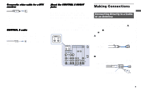
Some DTV receiver terminals may be labeled, differently. If so, connect as follows - controller
 |
View all Sony KP-53HS10 manuals
Add to My Manuals
Save this manual to your list of manuals |
Page 16 highlights
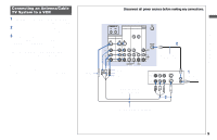
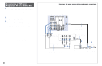
Connecting a DTV (digital television) receiver with the Y/PB/ PR (component video input) jacks 1 Attach the coaxial cable from the roof antenna to VHF/UHF on the DTV receiver. 2 Using three VIDEO cables, connect Y, PB and PR of COMPONENT VIDEO OUT on the DTV receiver to Y, PB and PR of VIDEO 5 (DTV) IN on the projection TV. 3 Using an AUDIO cable, connect LINE OUT on the DTV receiver to AUDIO of VIDEO 5 (DTV) IN on the projection TV (WhiteAUDIO Left, Red-AUDIO Right). 4 Select VIDEO 5 by the TV/VIDEO button. 5 Select the SET UP menu and set DTV INPUT to Y PB PR. (see "DTV INPUT" on page 43) Note: • Some DTV receiver terminals may be labeled differently. If so, connect as follows: Connect Y (green) to Y. Connect PB (blue) to CB, Cb or B-Y. Connect PR (red) to CR, Cr or R-Y. Disconnect all power sources before making any connections. 2 VMC-10HG (not supplied) PB Y PR CONTROL S IN OUT AUX IN OUT VIDEO 4 VIDEO 5 (DTV) SELECT DTV receiver IN VIDEO 1 VIDEO 3 HD VD S VIDEO VIDEO L (MONO) AUDIO R Y Y/G L PB PB/B (MONO) PR PR/R R COMPONENT AUDIO VHF/UHF VIDEO L AUDIO R AUDIO-R AUDIO-L VHF/UHF (DTV) 1 Roof Antenna RK-74A (not supplied) S VIDEO VIDEO 1 2 L (MONO) R 1 2 AUDIO OUT Y PB 3 PR VIDEO OUT 3 12
-
 1
1 -
2
-
3
-
4
-
5
-
6
-
7
-
8
-
9
-
10
-
 11
11 -
 12
12 -
 13
13 -
 14
14 -
 15
15 -
 16
16 -
 17
17 -
 18
18 -
 19
19 -
 20
20 -
 21
21 -
22
-
23
-
24
-
25
-
26
-
27
-
28
-
29
-
30
-
31
-
32
-
33
-
34
-
35
-
36
-
37
-
38
-
39
-
40
-
41
-
42
-
43
-
44
-
45
-
46
-
47
-
48
-
49
-
50
-
51
-
52
-
53
-
54
-
55
-
56
-
57
-
58
-
59
-
60
-
61
-
62
-
63
-
64
-
65
-
66
 |
 |
