Sony KP-53HS10 Operating Instructions - Page 22
Connecting a DVD Player With Component Video Output Connectors, Connect Y green to Y. - picture
 |
View all Sony KP-53HS10 manuals
Add to My Manuals
Save this manual to your list of manuals |
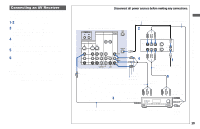
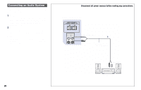
Page 22 highlights
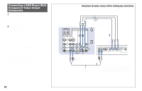
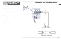
Connecting a DVD Player With Component Video Output Connectors 1 Using an AUDIO cable, connect AUDIO R and L of LINE OUT on the DVD Player to AUDIO R and L of VIDEO 4 IN or VIDEO 5 (DTV) IN on the projection TV (White-AUDIO Left, Red-AUDIO Right). 2 Using three VIDEO cables, connect Y, PB and PR of the COMPONENT VIDEO OUT on the DVD Player to Y, PB and PR of VIDEO 4 IN or VIDEO 5 (DTV) IN on the projection TV. Notes: • If your DVD Player has 480p format capability, connect it to the Y, PB and PR of VIDEO 5 (DTV) IN on the projection TV. • Some DVD Player terminals may be labeled differently. If so, connect as follows: Connect Y (green) to Y. Connect PB (blue) to CB, Cb or B-Y. Connect PR (red) to CR, Cr or R-Y. • Since the high quality pictures on a DVD disc contain a lot of information, picture noise may appear. In this case, adjust NR in the VIDEO menu. (see "NR" on page 35) Disconnect all power sources before making any connections. PR PB (Rear of projection TV) Y CONTROL S IN OUT IN OUT VIDEO 4 VIDEO 5 (DTV) SELECT VMC-10HG (not supplied) AUX IN VIDEO 1 VIDEO 3 HD VD S VIDEO VIDEO L (MONO) AUDIO R Y Y/G L PB PB/B (MONO) PR PR/R R COMPONENT AUDIO VHF/UHF VIDEO L AUDIO R 2 PR PB Y DVD LINE OUT S VIDEO OUT COMPONENT VIDEO OUT S-LINK DIGITAL OUT R-AUDIO 1-L VIDEO Y PB PR OPTICAL COAXIAL AUDIO-L AUDIO-R 1 RK-74A (not supplied) Connect the DVD Player directly to the projection TV. Connecting the DVD Player through other video equipment will cause unwanted picture noise. 18
-
 1
1 -
2
-
3
-
4
-
5
-
6
-
7
-
8
-
9
-
10
-
11
-
12
-
13
-
14
-
15
-
16
-
 17
17 -
 18
18 -
 19
19 -
 20
20 -
 21
21 -
 22
22 -
 23
23 -
 24
24 -
 25
25 -
 26
26 -
 27
27 -
28
-
29
-
30
-
31
-
32
-
33
-
34
-
35
-
36
-
37
-
38
-
39
-
40
-
41
-
42
-
43
-
44
-
45
-
46
-
47
-
48
-
49
-
50
-
51
-
52
-
53
-
54
-
55
-
56
-
57
-
58
-
59
-
60
-
61
-
62
-
63
-
64
-
65
-
66
 |
 |
