Sony PCV-L640 Reference Manual
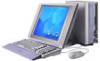
Sony PCV-L640 - Vaio Slimtop Computer Manual
 |
View all Sony PCV-L640 manuals
Add to My Manuals
Save this manual to your list of manuals |
Sony PCV-L640 manual content summary:
- Sony PCV-L640 | Reference Manual - Page 1
- Sony PCV-L640 | Reference Manual - Page 2
of their respective owners. Owner's Record The model number and serial number are located on the back of your VAIO® computer. Record the serial number in the space provided here. Refer to the model and serial number when you call your Sony Service Center. Model Number: PCV-L640 Serial Number - Sony PCV-L640 | Reference Manual - Page 3
iii VAIO Computer Reference Manual Safety Information and Caution CD-RW Laser Diode Properties Max. Laser output (read) UJDA310V UJDA310T UJDA320 1.8 mW 1.8 mW 1.8 mW Max. Laser output (write) UJDA310V UJDA310T UJDA320 21 mW 21 mW - Sony PCV-L640 | Reference Manual - Page 4
ADSL modele modem, afin de réduire les risques d'incendie, n'utilisez qu'un cordon de communication N0. 26 AWG ou plus gros. For questions regarding your product or for the Sony Service Center nearest you, call 1-888-476-6972 in the United States or 1-800-961-7669 in Canada. Sony Customer Support - Sony PCV-L640 | Reference Manual - Page 5
VAIO Computer Reference Manual Regulatory Information Declaration of Conformity Trade Name: SONY Model No.: PCV-L640 Responsible Party: Sony Electronics Inc. Address: 1 Sony Drive digital device, pursuant to Part 15 of the Rules. in accordance with the instructions, may cause harmful - Sony PCV-L640 | Reference Manual - Page 6
the trouble is causing harm to the telephone network, the telephone company may request that you remove the equipment from the network until the problem is resolved. Repair of this equipment should be made only by a Sony Service Center or Sony authorized agent. For the Sony Service Center nearest - Sony PCV-L640 | Reference Manual - Page 7
VAIO Computer Reference Manual Telephone Consumer Guidelines (Canada) Please refer to your telephone directory under 'Privacy Issues' and/or 'Terms of Service batteries to your nearest Sony Service Center or Factory Service Center. ✍ In to the manufacturer's instructions. ! The battery pack - Sony PCV-L640 | Reference Manual - Page 8
their own protection that the electrical ground connections of the power utility, telephone lines and internal metallic water pipe system é aux conditions énoncées cidessus n'empêche pas la dégradation du service dans certaines situations. Les réparations de matériel homologué doivent être coordonn - Sony PCV-L640 | Reference Manual - Page 9
ix VAIO Computer Reference Manual ensemble. Cette précaution est particulièrement importante dans les régions rurales. Avertissement: L'utilisateur ne doit pas tenter de faire ces raccordements lui-même; il doit avoir recours à un service d'inspection des installations électriques, ou à un é - Sony PCV-L640 | Reference Manual - Page 10
- Sony PCV-L640 | Reference Manual - Page 11
iii Regulatory Information v FCC Part 68 vi Telephone Consumer Protection Chapter 1 - Identifying Components Front View 2 Drives 3 Buttons and Switches 4 Indicators 5 Connectors the CMOS Setup Utility 14 Changing the Display's Power Management Settings 15 Configuring the System Board 17 - Sony PCV-L640 | Reference Manual - Page 12
VAIO Slimtop™ Reference Manual Header 48 Diskette Drive (FLOPPY) Connector 49 IDE Connectors 50 PCI Slot Connectors 51 Memory Module (DIMM) Connectors 52 Power (ATX PWR) LINE OUT Connectors 61 PHONE and MIC Connectors 62 Sony Memory Stick Slot Connector 63 i.LINK Interface Header Connectors - Sony PCV-L640 | Reference Manual - Page 13
CMOS Setup Options STANDARD CMOS SETUP Screen 76 BIOS FEATURES SETUP Screen 77 CHIPSET FEATURES SETUP Screen 80 POWER MANAGEMENT SETUP Screen 82 PNP AND PCI System I/O Address Map 93 Memory Map 95 Chapter 9 - Specifications Processor 97 Chipset 97 PCI Bus 97 Memory Modules (DIMMs 97 DIMM - Sony PCV-L640 | Reference Manual - Page 14
xiv VAIO Slimtop™ Reference Manual Audio 99 Communications 99 I/O and Expansion Slots 99 i.LINK Interface 100 Ethernet Interface 100 Drives and Controllers 100 System CMOS 101 - Sony PCV-L640 | Reference Manual - Page 15
Chapter 1 Identifying Components The following sections identify and describe each component that is visible from the exterior of the VAIO® Computer. Internal components are identified in Chapters 3, 4, and 5 of this manual. 1 - Sony PCV-L640 | Reference Manual - Page 16
2 VAIO Slimtop™ Reference Manual Front View FD DISC HD Flip-down panel SHA0001.VSD - Sony PCV-L640 | Reference Manual - Page 17
Components 3 FD DISC HD CD-RW disc drive Floppy disk drive SHA0002.VSD Drive Diskette drive CD-RW drive* Description 3.5-inch, 1.44 Mbyte. CD-ROM disc read: 20X (maximum performance). CD-R disc read: 20X (maximum performance). CD-R disc write: 4X (maximum performance). CD-RW disc read: 14X - Sony PCV-L640 | Reference Manual - Page 18
4 VAIO Slimtop™ Reference Manual Buttons and Switches Power on/off Manual eject hole Floppy disk eject FD DISC HD CD-RW disc eject Button or switch Power/Standby switch Floppy disk eject button CD-RW disc eject button Emergency eject hole Description Turns system power on and off. Ejects a - Sony PCV-L640 | Reference Manual - Page 19
DISC HD Diskette drive access indicator CD-RW drive access indicator Hard drive access indicator SHA0004.VSD Indicator Power/Standby indicator Diskette drive access indicator CD-RW drive access indicator Hard disk drive access indicator Description Standby (amber) indicates the computer is in - Sony PCV-L640 | Reference Manual - Page 20
6 VAIO Slimtop™ Reference Manual Connectors FD DISC HD MIC PHONES VOLUME i.LINK USB SHA0005. the i.LINK connector on the back of the system. A 6-pin i.LINK connector can supply power from the computer to the device if the device also has a 6-pin i.LINK connector. A 4-pin i.LINK connector - Sony PCV-L640 | Reference Manual - Page 21
Slots Identifying Components 7 FD DISC HD PC Card Slot Memory Stick Media Slot SHA0006.VSD Slot PC Card Slot Memory Stick® Media Slot Description Accommodates one Type I or Type II PCMCIA card. Accommodates Memory Stick media. - Sony PCV-L640 | Reference Manual - Page 22
device that has a 6-pin i.LINK connector. Connects to VAIO Slimtop™ LCD monitor. Connects to keyboard. * To connect to a 6-pin i.LINK device, use the i.LINK connector on the back of the system. A 6-pin i.LINK connector can supply power from the computer to the device if the device also has a 6-pin - Sony PCV-L640 | Reference Manual - Page 23
Identifying Components 9 I/O Connectors The following section identifies the various I/O connectors. PRINTER Port The PRINTER port is a standard 25-pin DB-25 female connector assigned as LPT1. 13 1 25 14 KY0005.VSD SERIAL Port The SERIAL port is a standard 9-pin DB-9 male connector assigned - Sony PCV-L640 | Reference Manual - Page 24
10 VAIO Slimtop™ Reference Manual USB Connectors A USB connector is located on the front and real panels. Rear panel Front panel KY0003.VSD PHONE, MIC, LINE IN, and LINE OUT - Sony PCV-L640 | Reference Manual - Page 25
. MAN009.VSD KY0004.VSD ! Do not connect any LCD monitor other than the Sony VAIO Slimtop LCD monitor. KEYBOARD/MOUSE The KEYBOARD/MOUSE connector is a mini DIN-type female connector that can be used for the supplied VAIO Smart convertible keyboard with wheel mouse, and a standard PS/2 keyboard - Sony PCV-L640 | Reference Manual - Page 26
12 VAIO Slimtop™ Reference Manual LINE and PHONE The LINE and PHONE jacks are physically identical and have identical connections. They are standard RJ-11 female phone jacks. However, the - Sony PCV-L640 | Reference Manual - Page 27
Chapter 2 Configuring Your System This chapter contains information on configuring your system. Configuring your system can consist of the following: ❑ Making changes to the CMOS settings ❑ Making changes to the display's power management settings ❑ Changing the system board jumper position 13 - Sony PCV-L640 | Reference Manual - Page 28
14 VAIO Slimtop™ Reference Manual Accessing the CMOS Setup Utility You must access the CMOS Setup Utility to make changes to the CMOS settings (see "CMOS Setup Options" on page - Sony PCV-L640 | Reference Manual - Page 29
then click Control Panel. 2 Click the Power Management icon. The Power Management Properties dialog box opens, with the Power Schemes tab displayed. 3 Select the power scheme that is most appropriate for the way you use your computer. To change a power scheme, change the settings for System standby - Sony PCV-L640 | Reference Manual - Page 30
16 VAIO Slimtop™ Reference Manual The Turn off monitor option allows you to specify the period of inactivity (in minutes) that you want to elapse before your monitor turns off when your computer is running on AC power. The display reactivates when you move the mouse or press a key. The Turn off hard - Sony PCV-L640 | Reference Manual - Page 31
never need changing unless otherwise directed by a technical support or service technician. ! Before opening the system, save any open files, exit Windows, turn off the power of the computer and all attached peripherals, and unplug the power cord. CMOS Jumper The CMOS jumper provides two modes - Sony PCV-L640 | Reference Manual - Page 32
18 VAIO Slimtop™ Reference Manual To change the CMOS jumper, perform the following steps: 1 Remove the system cover (see "Removing the System Cover" on page 24). 2 Set the jumper as directed by a service technician (also see "CMOS Jumper" on page 67). O1 2 3 4 5 6 N 123 Normal CMOS Clear KY0 3 - Sony PCV-L640 | Reference Manual - Page 33
Multiplier Switches The computer ships with the FREQ Ratio multiplier set to X6.0 (see SW table for positions of SW 1 through 4). Changing the FREQ Ratio multiplier will not change the speed of your CPU. Do not change the position of any switch unless directed by a technical support person. O1 - Sony PCV-L640 | Reference Manual - Page 34
20 VAIO Slimtop™ Reference Manual AGP_INT Switch You can enable or disable the onboard AGP interrupt. To enable or disable the AGP_INT, perform the following steps: 1 Remove the system cover ( - Sony PCV-L640 | Reference Manual - Page 35
Configuring Your System 21 VGA Switch You can enable or disable the onboard VGA controller if you install a VGA PCI add-in card. To enable or disable the onboard VGA, perform the following steps: 1 Remove the system cover (see "Removing the System Cover" on page 24). 2 Set the VGA switch (SW6) to ON - Sony PCV-L640 | Reference Manual - Page 36
22 - Sony PCV-L640 | Reference Manual - Page 37
This chapter describes removing, installing, and replacing major components for upgrading, reconfiguring, and troubleshooting the components. ! Before opening the system unit, save any open files, exit Windows, turn off the power of the computer and all attached peripherals, and then unplug the - Sony PCV-L640 | Reference Manual - Page 38
24 VAIO Slimtop™ Reference Manual Removing the System Cover You must remove the system cover to access the system board, add-in cards, power supply, battery, and internal drives. 1 From the rear of the unit, push down on the two tabs that secure the system cover to the chassis. 2 Slide the system - Sony PCV-L640 | Reference Manual - Page 39
from the rear of the unit. 3 Carefully slide the system cover back until the tabs snap into place. Check the front to make sure all drives and connectors are correctly aligned. 3 3 KY0077.VSD - Sony PCV-L640 | Reference Manual - Page 40
VAIO Slimtop™ Reference Manual Installing an Add-In Card ! Before opening the system unit, save any open files, exit Windows, turn off the power of the computer and all attached peripherals, and then unplug the power cables to the card (see the instructions that came with the add-in card). 5 Replace the - Sony PCV-L640 | Reference Manual - Page 41
any open files, exit Windows, turn off the power of the computer and all attached peripherals, and then unplug the power cord. 1 Remove the system cover (see a precaution, touch any exposed metal part on the metal chassis (preferably the metal part on the power supply) before handling an add-in card - Sony PCV-L640 | Reference Manual - Page 42
28 VAIO Slimtop™ Reference Manual 5 If you do not replace the card or install another add-in card, install a slot cover over the vacant slot at the rear of the chassis (see "Covering an Open I/O Slot" on page 45). 6 Replace the system cover (see "Replacing the System Cover" on page 25). - Sony PCV-L640 | Reference Manual - Page 43
29 Setting the Configuration Switches ! Before opening the system unit, save any open files, exit Windows, turn off the power of the computer and all attached peripherals, and then unplug the power cord. 1 Remove any add-in cards (see "Removing an Add-in Card" on page 27). 2 Set the switches as - Sony PCV-L640 | Reference Manual - Page 44
30 VAIO Slimtop™ Reference Manual Setting the CMOS Jumper ! Before opening the system unit, save any open files, exit Windows, turn off the power of the computer and all attached peripherals, and then unplug the power cord. 1 Remove the system cover (see "Removing the System Cover" on page 24). 2 - Sony PCV-L640 | Reference Manual - Page 45
the lithium battery if your computer consistently loses the date or time settings after turning it off. The lithium battery has a typical life of three years, after which the battery may be too weak to power the CMOS memory. ! Sony recommends that you use an authorized service dealer to replace the - Sony PCV-L640 | Reference Manual - Page 46
32 VAIO Slimtop™ Reference Manual 8 Carefully reach under the ribbon cable with your finger and push on the battery-eject lever (see diagram). One side of the battery pops up. KY00 ! Be carefull not to dislodge the ribbon cable. If it becomes dislodged, you may have to bring the unit in to a Sony- - Sony PCV-L640 | Reference Manual - Page 47
main menu using the arrow keys, then press Enter. 16 Type Y, then press Enter to save the changes and exit the CMOS Setup Utility. The computer's CMOS settings are now restored. - Sony PCV-L640 | Reference Manual - Page 48
34 VAIO Slimtop™ Reference Manual Installing System Memory ! Before opening the system unit, save any open files, exit Windows, turn off the power of the computer and all attached peripherals, and then unplug the power cord. 1 If necessary, remove the memory module you wish to replace (see " - Sony PCV-L640 | Reference Manual - Page 49
O1 2 3 4 5 6 N Pin 1 side DIMM2 DIMM1 Press down here Handles Memory module (DIMM) 1 Indicates pin 1 OM04586.VSD 5 Carefully but firmly insert the edge Cover" on page 25). Your computer automatically recognizes the extra memory and configures itself accordingly when you turn it on. - Sony PCV-L640 | Reference Manual - Page 50
36 VAIO Slimtop™ Reference Manual Removing a Memory Module You may need to remove a memory module if you change the memory configuration or replace a bad module. ! Before opening the system unit, save any open files, exit Windows, turn off the power of the computer and all attached peripherals, and - Sony PCV-L640 | Reference Manual - Page 51
, and Replacing Components 37 3 Remove the two screws that secure the hard drive carrier to the diskette drive housing. MAN002A.VSD 4 Lift up the hard drive carrier about ½ inch (until the tabs reach the stops), then pull sideways (away from the front panel) until the hard drive carrier is clear. - Sony PCV-L640 | Reference Manual - Page 52
38 VAIO Slimtop™ Reference Manual 5 Flip the hard drive carrier upside down and let it rest on the power supply while you remove DIMM #1. MAN003.VSD 6 Push out the handle on each side of the memory module to eject the module from its socket. Push out Handles KY0042.VSD - Sony PCV-L640 | Reference Manual - Page 53
in a static-free bag. KY ! Touch any exposed metal part of the chassis to discharge static electricity in your body before handling the memory module. ✍ If the memory module you removed is DIMM #2, stop. Otherwise, continue. 8 Flip the hard drive carrier back to its normal position. 9 Insert the - Sony PCV-L640 | Reference Manual - Page 54
40 VAIO Slimtop™ Reference Manual 10 Replace the two screws that secure the hard drive carrier to the diskette drive housing. ✍ Be sure you reattach the ground wire located at each screw. 11 Replace the system cover (see "Replacing the System Cover" on page 25). - Sony PCV-L640 | Reference Manual - Page 55
, save any open files, exit Windows, turn off the power of the computer and all attached peripherals, and then unplug the power cord. ✍ Be sure to back up any files on your hard drive that you want to preserve before you replace the drive. 1 Remove the system cover (see "Removing the System Cover - Sony PCV-L640 | Reference Manual - Page 56
VAIO Slimtop™ Reference Manual 4 Unplug the ribbon cable and power supply cable from the hard drive connectors. MAN004.VSD 5 Remove the four screws that secure the hard drive to the bottom of the drive carrier. 6 Remove the hard drive from the drive carrier. 7 Set the jumpers on the new hard drive - Sony PCV-L640 | Reference Manual - Page 57
Replace the two screws that secure the hard drive carrier to the diskette drive carrier. ✍ Be sure to reattach the ground wire at each screw location. You might need long-nose pliers to reach the ground wire closest to the drive's power-supply connector. 14 Replace the system cover (see "Replacing - Sony PCV-L640 | Reference Manual - Page 58
44 VAIO Slimtop™ Reference Manual Removing a Slot Cover You remove a slot cover when you install an add-in card that occupies a previously-empty slot. 1 Lay the system on its side - Sony PCV-L640 | Reference Manual - Page 59
Components 45 Covering an Open I/O Slot Slot covers prevent air from escaping through the empty hole. If air escapes, the components inside the computer cannot be properly cooled. This may damage some components, especially the main processor (which generates the most heat). 1 Fit the bottom end of - Sony PCV-L640 | Reference Manual - Page 60
46 - Sony PCV-L640 | Reference Manual - Page 61
each connector and jumper on the system board. Primary IDE CTRL Secondary IDE PWR Power CPU CPU Fan Printer Wake On LAN Serial CMOS VGA Monitor USB1 Line In Line Slot Battery Front Panel header USB2 i.LINK IEEE-1394 Floppy Sony Memory Stick PCMCIA Socket Memory Volume Phone Mic OM04581.VSD 47 - Sony PCV-L640 | Reference Manual - Page 62
48 VAIO Slimtop™ Reference Manual Connectors Front Panel Header The front panel header is a (MODEM) Reserved LED3 LED4 POWER SW GND Description +5V from power supply. Connects to LED on DVD-ROM. Connects to LED on floppy disk drive. Connects to LED on IDE hard disk drive. Connects to LED on modem - Sony PCV-L640 | Reference Manual - Page 63
System Board 49 Diskette Drive (FLOPPY) Connector The FLOPPY connector is a 26-pin connector for a slim notebook-type diskette drive. O1 2 3 4 5 6 N FLOPPY OM04701H.VSD - Sony PCV-L640 | Reference Manual - Page 64
50 VAIO Slimtop™ Reference Manual IDE Connectors There are two IDE (Integrated Drive Electronics) connectors: a Primary IDE and a Secondary IDE connector. The Primary IDE connector is a 40-pin 2.54 mm pitch header-type connector for the 3.5-inch hard disk drive. The Secondary IDE connector is a 50- - Sony PCV-L640 | Reference Manual - Page 65
cards. The PCI slot connectors are occupied by the Ethernet card (slot #1) and the fax/modem card (slot #2). The PCI slots in the riser card support 32-bit 5V and Universal (3.3/5V) PCI add-in cards. PCI slot for riser card O1 2 3 4 5 6 N OM04599B.VS Two PCI slot connectors PCI riser card - Sony PCV-L640 | Reference Manual - Page 66
52 VAIO Slimtop™ Reference Manual Memory Module (DIMM) Connectors O1 2 3 4 5 6 N DIMM1 DIMM2 OM04710A.VSD Both sides of each Dual Inline Memory Module (DIMM) look very similar. The side with pin 1 has a small "1" to the left of pin 1. Be sure to orient a DIMM correctly in the DIMM - Sony PCV-L640 | Reference Manual - Page 67
board. ATX PWR 10 20 O1 2 3 4 5 6 N 1 11 Power connector Pin # 1 2 3 4 Name +3.3V +3.3V GND +5V 5 GND 6 +5V 7 GND 8 PWRGD (power good) 9 +5VSB 10 +12V OM04701I.VSD Pin # 11 12 13 14 15 16 17 18 19 20 Name +3.3V -12V GND PS-ON# (power supply remote on/off control) GND GND GND - Sony PCV-L640 | Reference Manual - Page 68
54 VAIO Slimtop™ Reference Manual Fan (CPU FAN, CTRL PWR) Connectors The CPU Fan connector is a 1 x 3-pin straight header connector that controls the CPU cooling fan. The CTRL PWR connector is a 2 x 3-pin connector that controls the power supply cooling fan. It connects to P3 from the power supply. - Sony PCV-L640 | Reference Manual - Page 69
/Mouse (KB/MOUSE) Connector The combination keyboard/mouse connector is a 6-pin female PS/2® type (mini-DIN) connector that can accommodate the supplied VAIO Smart convertible keyboard and wheel mouse, or a PS/2 keyboard only. KB/MOUSE 1 6 O1 2 3 4 5 6 N Keyboard/Mouse connector Pin Signal Name - Sony PCV-L640 | Reference Manual - Page 70
56 VAIO Slimtop™ Reference Manual USB Connectors There are two USB ports that permit connection of two USB accessible from the front panel. USB2 USB1 O1 2 3 4 5 6 N USB1 connector (rear panel) Pin Signal Name 1 Power 2 USBP0# 3 USBP0 4 GND USB2 connector (front panel) Pin Signal Name - Sony PCV-L640 | Reference Manual - Page 71
System Board 57 PRINTER, SERIAL, and VGA MONITOR Connectors The SERIAL connector is a DB-9 male connector. The PRINTER connector is a DB-25 female connector. The VGA MONITOR connector is a 15-pin D-sub female connector. PRINTER 13 1 25 14 SERIAL 1 5 6 9 VGA MONITOR 5 1 15 11 O1 2 3 - Sony PCV-L640 | Reference Manual - Page 72
58 VAIO Slimtop™ Reference Manual SERIAL 1 connector Pin Signal Name 1 DCD 2 RXD# 3 TXD# 4 DTR# 5 GND 6 DSR 7 RTS 8 CTS 9 RI VGA MONITOR connector Pin Signal Name 1 RED 2 GREEN 3 BLUE 4 GND 5 DDC - Sony PCV-L640 | Reference Manual - Page 73
is a 40-pin MDR-type connector for the Sony VAIO Slimtop LCD monitor. LCD O1 2 3 4 5 6 N KY0094.VSD ! Do not connect any LCD other than the Sony VAIO Slimtop LCD monitor that came with the PCV-L640. The Sony VAIO Slimtop LCD monitor that came with the PCV-L620/L630 is not compatible with the - Sony PCV-L640 | Reference Manual - Page 74
60 VAIO Slimtop™ Reference Manual Wake On LAN (WOL_CON) Connector The WOL_CON connector is a 3-pin header connector that provides the Wake On LAN function to JP1 on the Ethernet card. WOL_CON 31 O1 2 3 4 5 6 N Wake On LAN connector Pin Signal 1 +5V SB 2 GND 3 WOL signal KY0096.VSD - Sony PCV-L640 | Reference Manual - Page 75
System Board 61 LINE IN and LINE OUT Connectors The LINE IN and LINE OUT jacks are stereo mini-jacks (3.5 mm) that connect to a stereo audio device (not an audio source from a video device). Connect a stereo audio output jack to the LINE IN jack, and the LINE OUT jack to a stereo audio input jack. - Sony PCV-L640 | Reference Manual - Page 76
62 VAIO Slimtop™ Reference Manual PHONE and MIC Connectors The PHONES jack is a stereo mini-jack (3.5 mm) that connects to headphones. The MIC jack is a stereo mini-jack (3.5 mm) that - Sony PCV-L640 | Reference Manual - Page 77
System Board 63 Sony Memory Stick Slot Connector The Sony Memory Stick slot connector is a 10-pin MCR 103-10S connector. O1 2 3 4 5 6 N Sony Memory Stick KY0097.VSD - Sony PCV-L640 | Reference Manual - Page 78
64 VAIO Slimtop™ Reference Manual i.LINK Interface Header Connectors The system board has two i.LINK (IEEE-1394) interface header connectors. A cable connects each 6-pin header connector to the riser card. - Sony PCV-L640 | Reference Manual - Page 79
to connect to devices that use a 6-pin* i.LINK (IEEE-1394) connector. i.LINK (front panel) i.LINK (rear panel) O1 2 3 4 5 6 N MAN001A.VSD * A 6-pin i.LINK connector can supply power from the computer to the device if the device also has a 6-pin i.LINK connector. A 4-pin i.LINK connector cannot - Sony PCV-L640 | Reference Manual - Page 80
66 VAIO Slimtop™ Reference Manual Auxiliary Audio In Connector The system board has an Auxiliary Audio In connector that is not used. Auxiliary Audio In (not used) 4 3 2 1 O1 2 3 4 5 6 N Auxiliary Audio - Sony PCV-L640 | Reference Manual - Page 81
VGA state (VGA). CMOS Jumper A jumper cap is installed on pins 1 and 2 (Normal) of the CMOS jumper when the computer is shipped. Do not move the jumper cap to the CMOS Clear position unless directed by a Sony-authorized technical support person. O1 2 3 4 5 6 N 123 Normal CMOS Clear KY0059.VSD - Sony PCV-L640 | Reference Manual - Page 82
68 VAIO Slimtop™ Reference Manual Configuration Switches (SW) A 6-switch dual inline package (DIP) provides configuration settings for FREQ Ratio (CPU multiplier), AGP_INT (AGP Interrupt) Enable/ Disable, and onboard VGA Enable/Disable. The CPU determines the CPU core frequency. The computer ships - Sony PCV-L640 | Reference Manual - Page 83
System Board 69 SW Function AGP_INT Enable AGP_INT Disable VGA Enable VGA Disable FREQ Ratio = X3.0 FREQ Ratio = X3.5 FREQ Ratio = X4.0 FREQ Ratio = X4.5 FREQ Ratio = X5.0 FREQ Ratio = X5.5 FREQ Ratio = X6.0 FREQ Ratio = X6.5 FREQ Ratio = X7.0 FREQ Ratio = X7.5 FREQ Ratio = X8.0 SW 1 N/A N/A N/A - Sony PCV-L640 | Reference Manual - Page 84
70 - Sony PCV-L640 | Reference Manual - Page 85
Chapter 5 Fax/Modem Card The K56flex™ technology/V.90-compatible data fax/modem card occupies PCI slot #2 in the Riser card. The fax/modem card has two RJ-11 jacks that are accessible from the rear panel: one to connect a telephone line, and one to connect a phone. TELEPHONE LINE Name TELEPHONE - Sony PCV-L640 | Reference Manual - Page 86
72 - Sony PCV-L640 | Reference Manual - Page 87
Chapter 6 Ethernet Card The Ethernet card occupies PCI slot #1 in the Riser card. The Ethernet card has one connector that is accessible from the rear panel. Ethernet Name Ethernet JP1 JP1 MAN010.VSD Connector Type RJ-45 3-pin header Description Connects to 10Base-T/100Base-TX Fast Ethernet - Sony PCV-L640 | Reference Manual - Page 88
74 - Sony PCV-L640 | Reference Manual - Page 89
" on page 14). The CMOS Setup Utility presents the following menu items on the main screen: ❑ STANDARD CMOS SETUP ❑ BIOS FEATURES SETUP ❑ CHIPSET FEATURES SETUP ❑ POWER MANAGEMENT SETUP ❑ PNP AND PCI SETUP ❑ LOAD SETUP DEFAULTS ❑ SUPERVISOR PASSWORDS ❑ USER PASSWORD ❑ IDE HDD AUTO DETECTION ❑ SAVE - Sony PCV-L640 | Reference Manual - Page 90
76 VAIO Slimtop™ Reference Manual STANDARD CMOS SETUP Screen Date (mm:dd:yy) Time (hh:mm:ss) HARD DISKS Primary Master Primary Slave Secondary Master Secondary Slave TYPE MODE Drive A Drive B Floppy 3 Mode Support Video Halt On [Sat, Oct 16 1999] [14 : 52: 53] [Auto] None User [AUTO] NORMAL LBA - Sony PCV-L640 | Reference Manual - Page 91
FEATURES SETUP Screen CPU Internal Core Speed Boot Virus Detection Processor Serial Number BIOS Update Quick Power On Self Test HDD Sequence SCSI/IDE First: Boot Sequence Floppy Disk Access Control IDE HDD Block Mode Sectors 700MHz* [Enabled] Disabled [Disabled] Enabled [Enabled] - Sony PCV-L640 | Reference Manual - Page 92
78 VAIO Slimtop™ Reference Manual HDD S.M.A.R.T. capability Silent Boot Boot Up Sound Boot Up Volume* PCI/VGA Palette Snoop Video ROM BIOS Shadow C8000 - CBFFF Shadow CC000 - CFFFF Shadow D0000 - D3FFF Shadow D4000 - D7FFF Shadow D8000 - DBFFF Shadow DC000 - DFFFF Shadow Boot Up NumLock Status - Sony PCV-L640 | Reference Manual - Page 93
Typematic Rate (Chars/Sec): Typematic Delay (Msec) Security Option PS/2 Mouse Function Control CMOS Setup Options 79 [6] 8 10 12 15 20 24 30 [250] 500 750 1000 [System] Setup [Auto] Enabled - Sony PCV-L640 | Reference Manual - Page 94
80 VAIO Slimtop™ Reference Manual CHIPSET FEATURES SETUP Screen SDRAM Configuration [By SPD] Disabled 7ns Fast Graphics Aperture Size [64MB] 128MB 256MB 4MB 8MB 16MB 32MB Video Memory Cache Mode [UC] USWC PCI 2.1 Support [Enabled] Disabled DRAM are 64 (Not 72) bits wide Data Integrity - Sony PCV-L640 | Reference Manual - Page 95
Onboard Serial Port 1 Onboard Serial Port 2 Onboard Parallel Port Parallel Port Mode ECP DMA Select* Onboard PCI IDE Enable IDE Ultra DMA Mode IDE0 Master PIO/DMA Mode IDE0 Slave PIO/DMA Mode IDE1 Master PIO/DMA Mode IDE1 Slave PIO/DMA Mode (each has identical - Sony PCV-L640 | Reference Manual - Page 96
82 VAIO Slimtop™ Reference Manual POWER MANAGEMENT SETUP Screen Power Management Video Off Option Video Off Method ** PM Timers ** HDD Power Down Suspend Mode* ** ACPI ** ACPI Mode [User Define] Disable Min Saving Max Saving [Suspend -> Off] Always On [DPMS OFF] DPMS Reduce ON Blank Screen V/H - Sony PCV-L640 | Reference Manual - Page 97
)] Ignore [(displays actual voltage)] Ignore [(displays actual voltage)] Ignore [(displays actual voltage)] Ignore [(displays actual voltage)] Ignore [(displays actual voltage)] Ignore * Displays only when Automatic Power Up is Everyday or By Date. † Displays only when Automatic - Sony PCV-L640 | Reference Manual - Page 98
84 VAIO Slimtop™ Reference Manual PNP AND PCI SETUP Screen PNP OS Installed Slot 1 IRQ Slot 2 IRQ PCI Latency Timer IRQ 3 Used By ISA IRQ 4 Used By ISA IRQ 5 Used - Sony PCV-L640 | Reference Manual - Page 99
IRQ 15 Used By ISA DMA 1 Used By ISA DMA 3 Used By ISA DMA 5 Used By ISA ISA MEM Block BASE USB IRQ ONB VGA BIOS First Onboard Audio Onboard Cardbus Onboard 1394 CMOS Setup Options 85 [No/ICU] Yes [No/ICU] Yes [No/ICU] Yes [No/ICU] Yes [No/ICU - Sony PCV-L640 | Reference Manual - Page 100
86 VAIO Slimtop™ Reference Manual LOAD SETUP DEFAULTS Screen Press Enter to load setup defaults password. Follow the prompts. IDE HDD AUTO DETECTION Screen Press Enter to auto-configure the hard disk drives. SAVE & EXIT SETUP Screen Press Enter to save changes in the CMOS and exit CMOS Setup Utility - Sony PCV-L640 | Reference Manual - Page 101
the following subjects: ❑ User and Supervisor password ❑ Beep code error messages ❑ PCI configuration status and error messages ❑ DMA channel assignments ❑ IRQ assignments ❑ System I/O address map ❑ Memory map 87 - Sony PCV-L640 | Reference Manual - Page 102
88 VAIO Slimtop™ Reference Manual About User and Supervisor Passwords The system allows you to specify up to two passwords (a User password and a Supervisor password) in the BIOS Setup Utility. The User password is required; the Supervisor password is optional. Access to the BIOS Setup Utility - Sony PCV-L640 | Reference Manual - Page 103
bootup, a single short beep signifies that the system is OK. Other beep patterns signify errors. The number of beeps indicates the specific error that occurred. The Sony Online Support technical representative will need to know how many beeps your system produces if there is an error, so be sure to - Sony PCV-L640 | Reference Manual - Page 104
VAIO Slimtop™ Reference Manual PCI is Full PCI I/O Port Conflict PCI IRQ Conflict PCI Memory Conflict Primary Boot Device Not Found Primary IDE Controller The designated primary boot device (hard disk drive, diskette drive, DVD-ROM drive, or network drive) could not be found. The primary IDE - Sony PCV-L640 | Reference Manual - Page 105
Miscellaneous Technical Information 91 DMA Channel Assignments This shows the factory default values. Windows 98 reassigns resources to best meet the needs of a particular configuration. DMA Channel 2 4 Default Assignment Standard diskette drive controller Direct memory access controller - Sony PCV-L640 | Reference Manual - Page 106
92 VAIO Slimtop™ Reference Manual IRQ Assignments IRQ # 00 01 02 03 04 06 07 08 09 host controller ACPI IRQ holder for PCI IRQ steering Realtek RTL8139(A/B/C/8130) PCI Fast Ethernet NIC Sony PCI to Memory Stick® interface controller Rage™ 128 Pro 4XL (English) ACPI IRQ holder for PCI IRQ steering - Sony PCV-L640 | Reference Manual - Page 107
resources System CMOS/real-time clock Motherboard resources Direct memory access controller Motherboard resources Direct memory access controller Programmable interrupt controller Motherboard resources Direct memory access controller Motherboard resources Numeric data processor Secondary IDE - Sony PCV-L640 | Reference Manual - Page 108
94 VAIO Slimtop™ Reference Manual Address Range (hex) 03F0h-03F1h 03F2h-03F5h 03F6h-03F6h 03F6h- B400h-B407h B800h-B807h B800h-B807h D000h-DFFFh D800h-D8FFh E400h-E43Fh E800h-E80Fh Description Motherboard resources Standard floppy disk controller Primary IDE controller (dual FIFO) Intel 82371AB/EB - Sony PCV-L640 | Reference Manual - Page 109
Rage 128 Pro 4XL (English) System board extension for ACPI BIOS System board extension for ACPI BIOS Ricoh RL5C475 CardBus controller Realtek RTL8139(A/B/C/8130) PCI Fast Ethernet NIC Lucent WinModem® Sony PCI to Memory Stick® interface controller Vortex AU8810 PCI audio Vortex AU8810 multifunction - Sony PCV-L640 | Reference Manual - Page 110
96 - Sony PCV-L640 | Reference Manual - Page 111
This chapter describes the technical specifications for the Sony PCV-L640 computer. Processor 700 MHz* Intel® Pentium® (none open) Memory Modules (DIMMs) Installed memory Maximum memory Voltage Pins SDRAM type 128 Mbytes SDRAM 256 Mbytes (128Mbytes in each socket) 3.3 V memory only 168-pins - Sony PCV-L640 | Reference Manual - Page 112
98 VAIO Slimtop™ Reference Manual DIMM Configurations DIMM1* 0, 16, 32, 64, 128 DIMM2* 0, 16, 32, 64, 128 * The PCV-L640 is shipped with 128 MB. SDRAM is expandable to 256 MB. Computer SDRAM is unbuffered DIMM, specification Rev. 1.0 or later. Supports SDRAM memory. Does not support EDO memory - Sony PCV-L640 | Reference Manual - Page 113
Specifications 99 Audio Sound chip Wave synthesis Sound effects Audio sampling rate 14.4 kbps maximum * Due to FCC limitations, the maximum permissible data speed is 53 kbps during download transmissions. Actual data speeds may vary due to a variety of factors. I/O and Expansion Slots Serial - Sony PCV-L640 | Reference Manual - Page 114
100 VAIO Slimtop™ Reference Manual i.LINK Interface Ports Speed Chipset Enable/disable function Two (one at front panel, one at rear panel) Up to 400 Mbps TI TSB12LV22 and TSB41LV03 OHCI From BIOS Ethernet Interface Connector Type of LAN Speed RJ-45 Ethernet 10Base-T/100Base-TX Drives and - Sony PCV-L640 | Reference Manual - Page 115
Specifications 101 System CMOS Make and model ROM Passwords Recovery boot block Power management Advanced features Plug and Play devices Special features Award 2Mbit flash-ROM User and supervisor passwords supported Supported APM 1.2 ACPI-1.0 compliant hardware for use with APM and PNP BIOS APIs - Sony PCV-L640 | Reference Manual - Page 116
102 - Sony PCV-L640 | Reference Manual - Page 117
27, 29, 30 address map, system 93 AGP_INT switch, changing 20 audio specifications 99 B battery - See lithium battery beep codes 89 BIOS - See Also CMOS BIOS features setup screen 77 C card, fax/modem 71, 73 CD-RW drive access indicator 5 disc eject button 4 emergency-eject hole 4 location of - Sony PCV-L640 | Reference Manual - Page 118
VAIO Computer Reference Manual Sony Memory Stick slot 63 system board 48 TELEPHONE 71, 73 USB 6, 56 VGA MONITOR 57 Wake On LAN 60 cover slot 44 system 24, 25 covering I/O slot 45 CPU See processor CPU Multiplier switch, changing 19 D DIMM 52 configurations 98 See Also memory modules diskette drive - Sony PCV-L640 | Reference Manual - Page 119
51 PHONE connector 10, 62 PNP and PCI setup screen 84 power connector 53 power management, configuring 15 PRINTER connector 9, 57 processor specifications 97 R radio interference v RAM - See Also system memory rear view 8 I/O connectors 9 recording ii regulatory information v removing add-in card - Sony PCV-L640 | Reference Manual - Page 120
106 VAIO Computer Reference Manual chipset 97 CMOS 101 communications 99 drives and controllers 100 graphics 98 i.LINK interface 100 I/O and expansion slots 99 L2 cache 98 memory module 97 PCI bus 97 processor 97 status and error messages 90 supervisor password 88 switches AGP_INT 20 CPU Multiplier
-
 1
1 -
 2
2 -
 3
3 -
 4
4 -
 5
5 -
 6
6 -
 7
7 -
8
-
9
-
10
-
11
-
12
-
13
-
14
-
15
-
16
-
17
-
18
-
19
-
20
-
21
-
22
-
23
-
24
-
25
-
26
-
27
-
28
-
29
-
30
-
31
-
32
-
33
-
34
-
35
-
36
-
37
-
38
-
39
-
40
-
41
-
42
-
43
-
44
-
45
-
46
-
47
-
48
-
49
-
50
-
51
-
52
-
53
-
54
-
55
-
56
-
57
-
58
-
59
-
60
-
61
-
62
-
63
-
64
-
65
-
66
-
67
-
68
-
69
-
70
-
71
-
72
-
73
-
74
-
75
-
76
-
77
-
78
-
79
-
80
-
81
-
82
-
83
-
84
-
85
-
86
-
87
-
88
-
89
-
90
-
91
-
92
-
93
-
94
-
95
-
96
-
97
-
98
-
99
-
100
-
101
-
102
-
103
-
104
-
105
-
106
-
107
-
108
-
109
-
110
-
111
-
112
-
113
-
114
-
115
-
116
-
117
-
118
-
119
-
120
 |
 |