Sony PCV-L640 Reference Manual - Page 61
System Board
 |
View all Sony PCV-L640 manuals
Add to My Manuals
Save this manual to your list of manuals |
Page 61 highlights
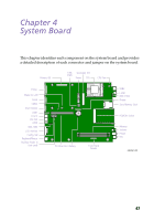
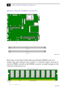
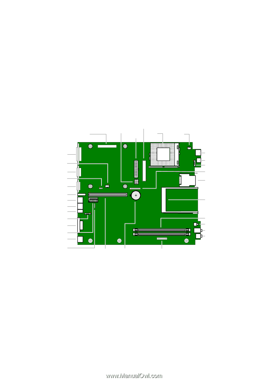
Chapter 4 System Board This chapter identifies each component on the system board and provides a detailed description of each connector and jumper on the system board. Primary IDE CTRL Secondary IDE PWR Power CPU CPU Fan Printer Wake On LAN Serial CMOS VGA Monitor USB1 Line In Line Out i.LINK IEEE-1394 LCD Monitor Config. SW Keyboard/Mouse Auxiliary Audio In (not used) O1 2 3 4 5 6 N PCI Riser Slot Battery Front Panel header USB2 i.LINK IEEE-1394 Floppy Sony Memory Stick PCMCIA Socket Memory Volume Phone Mic OM04581.VSD 47
-
 1
1 -
2
-
3
-
4
-
5
-
6
-
7
-
8
-
9
-
10
-
11
-
12
-
13
-
14
-
15
-
16
-
17
-
18
-
19
-
20
-
21
-
22
-
23
-
24
-
25
-
26
-
27
-
28
-
29
-
30
-
31
-
32
-
33
-
34
-
35
-
36
-
37
-
38
-
39
-
40
-
41
-
42
-
43
-
44
-
45
-
46
-
47
-
48
-
49
-
50
-
51
-
52
-
53
-
54
-
55
-
 56
56 -
 57
57 -
 58
58 -
 59
59 -
 60
60 -
 61
61 -
 62
62 -
 63
63 -
 64
64 -
 65
65 -
 66
66 -
67
-
68
-
69
-
70
-
71
-
72
-
73
-
74
-
75
-
76
-
77
-
78
-
79
-
80
-
81
-
82
-
83
-
84
-
85
-
86
-
87
-
88
-
89
-
90
-
91
-
92
-
93
-
94
-
95
-
96
-
97
-
98
-
99
-
100
-
101
-
102
-
103
-
104
-
105
-
106
-
107
-
108
-
109
-
110
-
111
-
112
-
113
-
114
-
115
-
116
-
117
-
118
-
119
-
120
 |
 |
47
Chapter 4
System Board
This chapter identifies each component on the system board and provides
a detailed description of each connector and jumper on the system board.
O
N
123456
Printer
Serial
VGA Monitor
USB1
Line In
Line Out
LCD Monitor
Keyboard/Mouse
Primary IDE
CPU
IEEE-1394
Front Panel
header
Memory
Volume
Phone
Mic
Wake On LAN
Floppy
Power
OM04581.VSD
USB2
Sony Memory Stick
CTRL
PWR
i.LINK
CMOS
i.LINK
IEEE-1394
CPU Fan
PCI Riser Slot
Battery
PCMCIA Socket
Secondary IDE
Config. SW
Auxiliary Audio In
(not used)