Sony PCV-L640 Reference Manual - Page 82
Configuration Switches (SW), The computer ships with AGP_INT SW 5 set to OFF Disable and VGA
 |
View all Sony PCV-L640 manuals
Add to My Manuals
Save this manual to your list of manuals |
Page 82 highlights
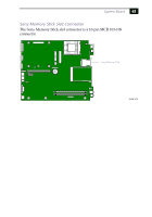
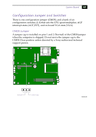
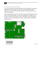
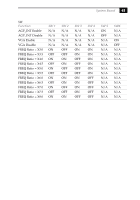
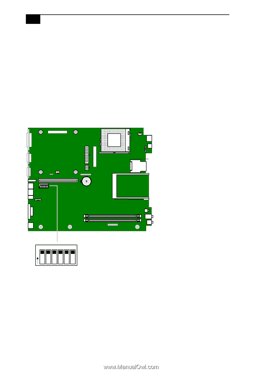
68 VAIO Slimtop™ Reference Manual Configuration Switches (SW) A 6-switch dual inline package (DIP) provides configuration settings for FREQ Ratio (CPU multiplier), AGP_INT (AGP Interrupt) Enable/ Disable, and onboard VGA Enable/Disable. The CPU determines the CPU core frequency. The computer ships with AGP_INT (SW 5) set to OFF (Disable) and VGA (SW 6) set to OFF (Disable), and with the FREQ Ratio multiplier set to X6.0 (see SW table for positions of SW 1 through 4). Do not change the position of any switch unless directed by a Sony-authorized technical support person. O1 2 3 4 5 6 N SW 123456 O N MAN005.VSD
-
 1
1 -
2
-
3
-
4
-
5
-
6
-
7
-
8
-
9
-
10
-
11
-
12
-
13
-
14
-
15
-
16
-
17
-
18
-
19
-
20
-
21
-
22
-
23
-
24
-
25
-
26
-
27
-
28
-
29
-
30
-
31
-
32
-
33
-
34
-
35
-
36
-
37
-
38
-
39
-
40
-
41
-
42
-
43
-
44
-
45
-
46
-
47
-
48
-
49
-
50
-
51
-
52
-
53
-
54
-
55
-
56
-
57
-
58
-
59
-
60
-
61
-
62
-
63
-
64
-
65
-
66
-
67
-
68
-
69
-
70
-
71
-
72
-
73
-
74
-
75
-
76
-
 77
77 -
 78
78 -
 79
79 -
 80
80 -
 81
81 -
 82
82 -
 83
83 -
 84
84 -
 85
85 -
 86
86 -
 87
87 -
88
-
89
-
90
-
91
-
92
-
93
-
94
-
95
-
96
-
97
-
98
-
99
-
100
-
101
-
102
-
103
-
104
-
105
-
106
-
107
-
108
-
109
-
110
-
111
-
112
-
113
-
114
-
115
-
116
-
117
-
118
-
119
-
120
 |
 |
VAIO Slimtop
™
Reference Manual
68
Configuration Switches (SW)
A 6-switch dual inline package (DIP) provides configuration settings for
FREQ Ratio (CPU multiplier), AGP_INT (AGP Interrupt) Enable/
Disable, and onboard VGA Enable/Disable. The CPU determines the
CPU core frequency.
The computer ships with AGP_INT (SW 5) set to OFF (Disable) and VGA
(SW 6) set to OFF (Disable), and with the FREQ Ratio multiplier set to
X6.0 (see SW table for positions of SW 1 through 4). Do not change the
position of any switch unless directed by a Sony-authorized technical
support person.
O
N
123456
MAN005.VSD
O
N
1
2
3
4
5
6
SW