Sony PCV-L640 Reference Manual - Page 79
i.LINK Connectors, i.LINK IEEE-1394
 |
View all Sony PCV-L640 manuals
Add to My Manuals
Save this manual to your list of manuals |
Page 79 highlights
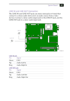
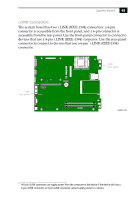
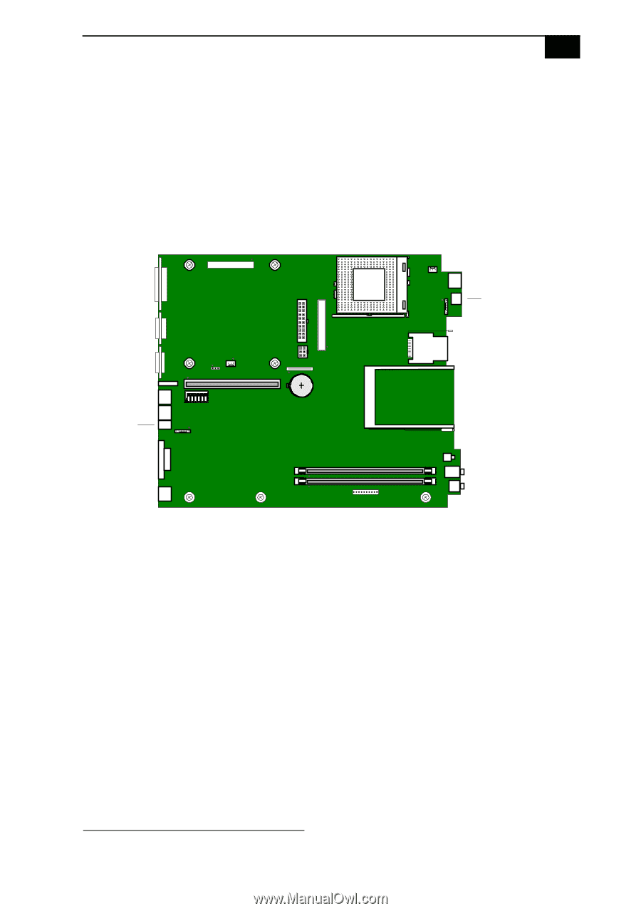
System Board 65 i.LINK Connectors The system board has two i.LINK (IEEE-1394) connectors: a 4-pin connector is accessible from the front panel, and a 6-pin connector is accessible from the rear panel. Use the front-panel connector to connect to devices that use a 4-pin i.LINK (IEEE-1394) connector. Use the rear-panel connector to connect to devices that use a 6-pin* i.LINK (IEEE-1394) connector. i.LINK (front panel) i.LINK (rear panel) O1 2 3 4 5 6 N MAN001A.VSD * A 6-pin i.LINK connector can supply power from the computer to the device if the device also has a 6-pin i.LINK connector. A 4-pin i.LINK connector cannot supply power to a device.
-
 1
1 -
2
-
3
-
4
-
5
-
6
-
7
-
8
-
9
-
10
-
11
-
12
-
13
-
14
-
15
-
16
-
17
-
18
-
19
-
20
-
21
-
22
-
23
-
24
-
25
-
26
-
27
-
28
-
29
-
30
-
31
-
32
-
33
-
34
-
35
-
36
-
37
-
38
-
39
-
40
-
41
-
42
-
43
-
44
-
45
-
46
-
47
-
48
-
49
-
50
-
51
-
52
-
53
-
54
-
55
-
56
-
57
-
58
-
59
-
60
-
61
-
62
-
63
-
64
-
65
-
66
-
67
-
68
-
69
-
70
-
71
-
72
-
73
-
 74
74 -
 75
75 -
 76
76 -
 77
77 -
 78
78 -
 79
79 -
 80
80 -
 81
81 -
 82
82 -
 83
83 -
 84
84 -
85
-
86
-
87
-
88
-
89
-
90
-
91
-
92
-
93
-
94
-
95
-
96
-
97
-
98
-
99
-
100
-
101
-
102
-
103
-
104
-
105
-
106
-
107
-
108
-
109
-
110
-
111
-
112
-
113
-
114
-
115
-
116
-
117
-
118
-
119
-
120
 |
 |
System Board
65
i.LINK Connectors
The system board has two i.LINK (IEEE-1394) connectors: a 4-pin
connector is accessible from the front panel, and a 6-pin connector is
accessible from the rear panel. Use the front-panel connector to connect to
devices that use a 4-pin i.LINK (IEEE-1394) connector. Use the rear-panel
connector to connect to devices that use a 6-pin
*
i.LINK (IEEE-1394)
connector.
*
A 6-pin i.LINK connector can supply power from the computer to the device if the device also has a
6-pin i.LINK connector. A 4-pin i.LINK connector cannot supply power to a device.
O
N
123456
i.LINK
(rear panel)
MAN001A.VSD
i.LINK
(front panel)