Sony PCV-LX910 System Reference Manual - Page 50
on Replace the system cover see
 |
View all Sony PCV-LX910 manuals
Add to My Manuals
Save this manual to your list of manuals |
Page 50 highlights
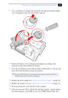
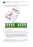
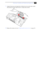
36 VAIO Slimtop™ System Reference Manual 4 Align the module over the appropriate socket, and note the location of pin 1 on the module and pin 1 on the socket. Memory module (DIMM) 1 Indicates pin 1 5 Carefully but firmly insert the edge of the module into the socket. 6 Press down firmly and evenly at both corners until the module is fully seated. ✍ When the module is fully seated, the latches on each side are straight up and locked into the slot on each side of the module. If the latches are not completely straight upright, continue to press down on each side of the module until the latches lock into place. 7 Replace the system cover (see "Replacing the System Cover" on page 25). Your computer automatically recognizes the extra memory and configures itself accordingly when you turn it on. No further action is required.
-
 1
1 -
2
-
3
-
4
-
5
-
6
-
7
-
8
-
9
-
10
-
11
-
12
-
13
-
14
-
15
-
16
-
17
-
18
-
19
-
20
-
21
-
22
-
23
-
24
-
25
-
26
-
27
-
28
-
29
-
30
-
31
-
32
-
33
-
34
-
35
-
36
-
37
-
38
-
39
-
40
-
41
-
42
-
43
-
44
-
 45
45 -
 46
46 -
 47
47 -
 48
48 -
 49
49 -
 50
50 -
 51
51 -
 52
52 -
 53
53 -
 54
54 -
 55
55 -
56
-
57
-
58
-
59
-
60
-
61
-
62
-
63
-
64
-
65
-
66
-
67
-
68
-
69
-
70
-
71
-
72
-
73
-
74
-
75
-
76
-
77
-
78
-
79
-
80
-
81
-
82
-
83
-
84
-
85
-
86
-
87
-
88
-
89
-
90
-
91
-
92
-
93
-
94
-
95
-
96
-
97
-
98
-
99
-
100
-
101
-
102
-
103
-
104
-
105
-
106
-
107
-
108
-
109
-
110
-
111
-
112
 |
 |
