Sony PCV-LX910 System Reference Manual - Page 60
Connectors, Front Panel Header
 |
View all Sony PCV-LX910 manuals
Add to My Manuals
Save this manual to your list of manuals |
Page 60 highlights
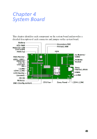
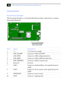
46 VAIO Slimtop™ System Reference Manual Connectors Front Panel Header The front panel header is a 10-pin header that provides connections to various front panel functions. O1 2 N Front panel header Pin # 1 2 3 4 5 6 7 Name +5 LED (CD-RW) LED (FDD) LED (HDD) LED (MODEM) Reserved LED3 8 LED4 9 POWER SW 10 GND Description +5V from power supply. Connects to LED on CD-RW. Connects to LED on floppy disk drive. Connects to LED on IDE hard disk drive. Connects to LED on modem card. Not used. Connects to Stand by/Sleep (red) signal from power supply. Connects to Power (green) anode signal from power supply. Connects to power switch. Connects to signal ground.
-
 1
1 -
2
-
3
-
4
-
5
-
6
-
7
-
8
-
9
-
10
-
11
-
12
-
13
-
14
-
15
-
16
-
17
-
18
-
19
-
20
-
21
-
22
-
23
-
24
-
25
-
26
-
27
-
28
-
29
-
30
-
31
-
32
-
33
-
34
-
35
-
36
-
37
-
38
-
39
-
40
-
41
-
42
-
43
-
44
-
45
-
46
-
47
-
48
-
49
-
50
-
51
-
52
-
53
-
54
-
 55
55 -
 56
56 -
 57
57 -
 58
58 -
 59
59 -
 60
60 -
 61
61 -
 62
62 -
 63
63 -
 64
64 -
 65
65 -
66
-
67
-
68
-
69
-
70
-
71
-
72
-
73
-
74
-
75
-
76
-
77
-
78
-
79
-
80
-
81
-
82
-
83
-
84
-
85
-
86
-
87
-
88
-
89
-
90
-
91
-
92
-
93
-
94
-
95
-
96
-
97
-
98
-
99
-
100
-
101
-
102
-
103
-
104
-
105
-
106
-
107
-
108
-
109
-
110
-
111
-
112
 |
 |

VAIO Slimtop™ System Reference Manual
46
Connectors
Front Panel Header
The front panel header is a 10-pin header that provides connections to various
front panel functions.
Pin #
Name
Description
1
+5
+5V from power supply.
2
LED (CD-RW)
Connects to LED on CD-RW.
3
LED (FDD)
Connects to LED on floppy disk drive.
4
LED (HDD)
Connects to LED on IDE hard disk drive.
5
LED (MODEM)
Connects to LED on modem card.
6
Reserved
Not used.
7
LED3
Connects to Stand by/Sleep (red) signal from power
supply.
8
LED4
Connects to Power (green) anode signal from power
supply.
9
POWER SW
Connects to power switch.
10
GND
Connects to signal ground.
O
12
Front panel header