Sony PDW510 Operation Manual - Page 16
Audio Functions
 |
View all Sony PDW510 manuals
Add to My Manuals
Save this manual to your list of manuals |
Page 16 highlights
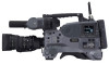
2-3 Audio Functions 1 Microphone 8 Built-in speaker Chapter 2 Locations and Functions of Parts and Controls 2 MIC IN connector 3 MIC LEVEL control 4 EARPHONE jack (rear, stereo) 7 ALARM volume control 6 MONITOR volume control 5 MONITOR switch and CH-1/2 / CH-3/4 switch 4 EARPHONE jack (front, monaural) Audio functions (1) a Microphone This is a super-cardioid directional monaural microphone with an external power supply (+48 V) system. b MIC IN (microphone input) connector (XLR type, 3-pin, female) Connect the supplied microphone to this connector. A microphone other than the supplied one may also be connected as long as it can operate with the power (+48 V) supplied from this connector. By fitting a 5-pin connector (service part number: A-1053453-A), you can also use a stereo microphone. c MIC (microphone) LEVEL control This control adjusts the audio level of the microphone connected to the MIC IN connector. d EARPHONE jack (front) (monaural, minijack) / EARPHONE jack (rear) (monaural/stereo switchable, minijack) You can monitor the E-E sound 1) during recording and playback sound during playback. Plugging an earphone into the jack automatically cuts off the built-in speaker. When an alarm is indicated, you can hear the alarm sound through the earphone. You can use the rear EARPHONE jack for stereo output, by setting the HEADPHONE OUT item in the AUDIO-1 page of the MAINTENANCE menu to "STREO". You can also connect a monaural earphone to the front jack and a monaural/stereo earphone set to the rear jack simultaneously. 1) E-E: Abbreviation of "Electric-to-Electric." In E-E mode, video and audio signals input to the camcorder are output after passing through internal electric circuits only. This can be used to check input signals. e MONITOR switch and CH-1/2 / CH-3/4 switch These switches together determine the channel selection for audio monitor output. MONITOR switch CH-1/2 / CH-3/4 switch MONITOR switch and CH-1/2 / CH-3/4 switch CH-1/2 / CH-3/4 switch: This determines the pair of audio channels selected with the MONITOR switch. CH-1/2 position: channels 1 and 2 CH-3/4 position: channels 3 and 4 The signals output from the AUDIO OUT connector and EARPHONE jacks also depend on the setting of this switch. MONITOR switch: This selects the audio monitor channels output to the monaural earphone or speaker, depending on the setting of the CH-1/2 / CH-3/4 switch. 16 2-3 Audio Functions
-
 1
1 -
2
-
3
-
4
-
5
-
6
-
7
-
8
-
9
-
10
-
 11
11 -
 12
12 -
 13
13 -
 14
14 -
 15
15 -
 16
16 -
 17
17 -
 18
18 -
 19
19 -
 20
20 -
 21
21 -
22
-
23
-
24
-
25
-
26
-
27
-
28
-
29
-
30
-
31
-
32
-
33
-
34
-
35
-
36
-
37
-
38
-
39
-
40
-
41
-
42
-
43
-
44
-
45
-
46
-
47
-
48
-
49
-
50
-
51
-
52
-
53
-
54
-
55
-
56
-
57
-
58
-
59
-
60
-
61
-
62
-
63
-
64
-
65
-
66
-
67
-
68
-
69
-
70
-
71
-
72
-
73
-
74
-
75
-
76
-
77
-
78
-
79
-
80
-
81
-
82
-
83
-
84
-
85
-
86
-
87
-
88
-
89
-
90
-
91
-
92
-
93
-
94
-
95
-
96
-
97
-
98
-
99
-
100
-
101
-
102
-
103
-
104
-
105
-
106
-
107
-
108
-
109
-
110
-
111
-
112
-
113
-
114
-
115
-
116
-
117
-
118
-
119
-
120
-
121
-
122
-
123
-
124
-
125
-
126
-
127
-
128
-
129
-
130
-
131
-
132
-
133
-
134
-
135
-
136
-
137
-
138
-
139
-
140
-
141
-
142
-
143
-
144
-
145
-
146
-
147
-
148
-
149
-
150
-
151
-
152
-
153
-
154
-
155
-
156
-
157
-
158
-
159
-
160
-
161
-
162
-
163
-
164
-
165
-
166
-
167
-
168
-
169
-
170
-
171
-
172
-
173
-
174
-
175
-
176
-
177
-
178
-
179
-
180
-
181
-
182
-
183
-
184
-
185
-
186
-
187
-
188
-
189
-
190
-
191
-
192
-
193
-
194
-
195
-
196
-
197
-
198
-
199
-
200
-
201
-
202
-
203
-
204
-
205
-
206
-
207
-
208
-
209
-
210
-
211
-
212
-
213
-
214
-
215
-
216
 |
 |
