Sony PDW510 Operation Manual - Page 20
For the PDW-510/510P, Viewfinder front-rear positioning lever - pdw 510 camcorder
 |
View all Sony PDW510 manuals
Add to My Manuals
Save this manual to your list of manuals |
Page 20 highlights
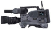
Chapter 2 Locations and Functions of Parts and Controls g Viewfinder The viewfinder lets you view the image in black and white while shooting, recording or playing back. It also displays various warnings and messages related to the settings or operating conditions of the camcorder, a zebra pattern, safety zone marker 1), and center marker 2). 1) The safety zone marker is a rectangle indicating the effective picture area. 2) The center marker indicates the center of the picture with a crosshair. For details, see 7-2-4 "Setting the Marker Display" on page 124. h Diopter adjustment ring Use this ring to adjust the viewfinder image for your vision. i Viewfinder front-rear positioning lever To adjust the viewfinder position in the front-rear direction, loosen this lever and the LOCK knob. After adjustment, retighten this lever and the LOCK knob. j Viewfinder left-right positioning ring Loosen this ring to move the viewfinder sideways. k Camera operator tally indicator This indicator lights while the camcorder is recording. Slide the window open when you shoot with your eye away from the viewfinder. This indicator flashes when the battery level is running low or the disc is almost full. l Viewfinder stopper Pull up this stopper to detach the viewfinder from the camera. m LOCK knob To adjust the viewfinder position in the front-rear direction, loosen this knob and the viewfinder front-rear positioning lever. After adjustment, retighten this knob and the viewfinder front-rear positioning lever. ws ASSIGN 3/4 switches qf FILTER selector qg ASSIGN. 1/2 switches qh SHUTTER selector qj AUTO W/B BAL switch wa TURBO GAIN button w; WHITE BAL switch ql OUTPUT/DCC selector qk GAIN selector Shooting and recording/playback functions (2) n FILTER selector Use this selector to select the most appropriate filter to match the light source illuminating the subject. When this selector is used with the display mode set to 3, the new setting appears on the viewfinder screen for about 3 seconds. (e.g.: FILTER: 3) The PDW-510/510P has one switchable filter, and the PDW-530/530P has two switchable filters. The relationships between the selector settings and filter selections as well as examples of filters for different shooting conditions are as follows. For the PDW-510/510P FILTER selector setting and filter selection FILTER selector setting 1 2 3 4 Filter selection 3200 K 5600 K + 1/8 ND 5600 K 5600 K + 1/64 ND Examples of shooting conditions and appropriate filters Shooting condition Sunrise and sunset; inside studio Clear skies Cloudy or raining Filter 1 (3200 K) 2 (5600 K + 1/8 ND) 3 (5600 K) 20 2-4 Shooting and Recording/Playback Functions
-
 1
1 -
2
-
3
-
4
-
5
-
6
-
7
-
8
-
9
-
10
-
11
-
12
-
13
-
14
-
 15
15 -
 16
16 -
 17
17 -
 18
18 -
 19
19 -
 20
20 -
 21
21 -
 22
22 -
 23
23 -
 24
24 -
 25
25 -
26
-
27
-
28
-
29
-
30
-
31
-
32
-
33
-
34
-
35
-
36
-
37
-
38
-
39
-
40
-
41
-
42
-
43
-
44
-
45
-
46
-
47
-
48
-
49
-
50
-
51
-
52
-
53
-
54
-
55
-
56
-
57
-
58
-
59
-
60
-
61
-
62
-
63
-
64
-
65
-
66
-
67
-
68
-
69
-
70
-
71
-
72
-
73
-
74
-
75
-
76
-
77
-
78
-
79
-
80
-
81
-
82
-
83
-
84
-
85
-
86
-
87
-
88
-
89
-
90
-
91
-
92
-
93
-
94
-
95
-
96
-
97
-
98
-
99
-
100
-
101
-
102
-
103
-
104
-
105
-
106
-
107
-
108
-
109
-
110
-
111
-
112
-
113
-
114
-
115
-
116
-
117
-
118
-
119
-
120
-
121
-
122
-
123
-
124
-
125
-
126
-
127
-
128
-
129
-
130
-
131
-
132
-
133
-
134
-
135
-
136
-
137
-
138
-
139
-
140
-
141
-
142
-
143
-
144
-
145
-
146
-
147
-
148
-
149
-
150
-
151
-
152
-
153
-
154
-
155
-
156
-
157
-
158
-
159
-
160
-
161
-
162
-
163
-
164
-
165
-
166
-
167
-
168
-
169
-
170
-
171
-
172
-
173
-
174
-
175
-
176
-
177
-
178
-
179
-
180
-
181
-
182
-
183
-
184
-
185
-
186
-
187
-
188
-
189
-
190
-
191
-
192
-
193
-
194
-
195
-
196
-
197
-
198
-
199
-
200
-
201
-
202
-
203
-
204
-
205
-
206
-
207
-
208
-
209
-
210
-
211
-
212
-
213
-
214
-
215
-
216
 |
 |
