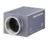
Sony XCDSX90 User Manual (XCDV60_V60CR_SX90_SX90CR_U100_U100CR_Technical_Manua - Page 11
Pan/Tilt, Brightness, Sharpness (Black and white models only), Saturation (Color models only), White
 |
View all Sony XCDSX90 manuals
Add to My Manuals
Save this manual to your list of manuals |
Page 11 highlights
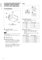
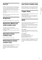
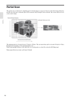
Functions Pan/Tilt Pan/Tilt is a function used to move a camera up and down or left and right. However this camera supports a video mode much smaller than the CCD's effective pixels by cutting out images from the whole screen. You can specify the portion to be cut out using Pan/Tilt commands. The variable range differs according to the selected video mode. When a video mode is changed, the pan/tilt values are set to the default setting. Brightness This feature controls the black level of a video image. Sharpness (Black and white models only) This feature controls the image quality. A smaller value makes the image softer, and a larger value makes it sharper. The Sharpness feature cannot be used together with the 3 × 3 filter. Saturation (Color models only) This feature controls the color density. White Balance (Color models only) This feature controls the white balance by setting the R and B levels relative to the G level. The camera also supports the Auto white balance by which the camera automatically adjusts the white balance. Hue (Color models only) When the white balance cannot be obtained with the R and B level adjustment, you can change the G level by hue adjustment. Normally use the default hue setting. Trigger Delay Issue of a trigger signal can be delayed from the external trigger inside the camera. This delay adjustment is useful to get an appropriate shooting timing when the position of the subject is not good at a regular trigger timing. GPIO A general-purpose I/O port with a 2-bit output and 2-bit input is assigned in the 12-pin connector. This port is used for reading information of external switches and sensors from the camera and controlling external devices. The output terminal is of the open-collector type and should be pulled outside of the camera (5 to 24 V). Note on input Connect to ISO (GND) using an input device with a minimum signal width of 0.5 msec and an input current of 0.5 mA or more. Note on output Use the following conditions: Recommended pull-up resistor: 4.7 kΩ Recommended pull-up voltage: 5 V Minimum signal width: 0.5 msec The camera is equipped with a protective resistor of 220 Ω. If the above conditions prove difficult in use, check the output voltage and determine the external pull-up resistor. 11
-
 1
1 -
2
-
3
-
4
-
5
-
 6
6 -
 7
7 -
 8
8 -
 9
9 -
 10
10 -
 11
11 -
 12
12 -
 13
13 -
 14
14 -
 15
15 -
 16
16 -
17
-
18
-
19
-
20
-
21
-
22
-
23
-
24
-
25
-
26
-
27
-
28
-
29
-
30
-
31
-
32
-
33
-
34
-
35
-
36
-
37
-
38
 |
 |
