Sony XCDSX90 User Manual (XCDV60_V60CR_SX90_SX90CR_U100_U100CR_Technical_Manua - Page 12
Strobe Control, Setting AE/AWB Control Frame and Parameters, Test Charts, Changing Bayer Patterns (
 |
View all Sony XCDSX90 manuals
Add to My Manuals
Save this manual to your list of manuals |
Page 12 highlights
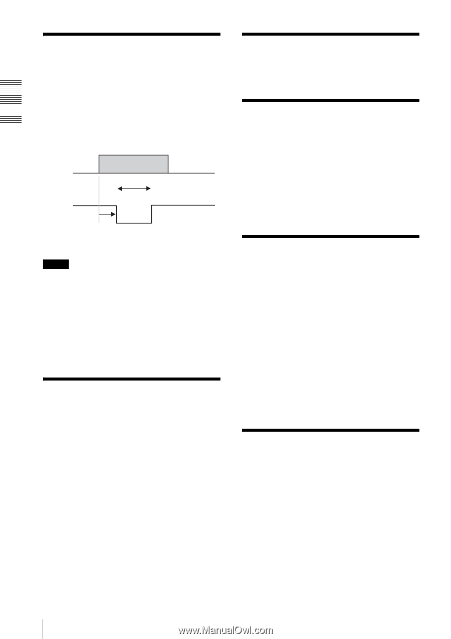
Functions Strobe Control A strobe control signal is assigned in the 12-pin connector. This allows direct command of lightemission from the strobe connected to the camera and controls the light-emission timing and the signal width. The output terminal is of the open-collector type and should be pulled at the strobe side. A strobe that emits light by short-circuiting the input to ground can be connected to the camera directly. Llight-emission timing Width Strobe output signal Delay Note Use the following conditions: Recommended pull-up resistor: 4.7 kΩ Recommended pull-up voltage: 5 V The camera is equipped with a protective resistor of 220 Ω. If the above conditions prove difficult in use, check the output voltage and determine the external pull-up resistor. The camera is capable of outputting a signal of about 10 microsecond width, although the rise time depends on the pull-up resistor. Setting AE/AWB Control Frame and Parameters The detection frame for Auto Exposure and Auto White Balance can be set. Determine the detection frame in percentage units taking the width and height of the output image as 100 %. The control speeds for Auto Exposure and Auto White Balance can also be set. Raise or lower the response speed for each application respectively. For Auto Exposure, the restart conditions can also be set, that is the conditions once Auto Exposure adjustment has concluded and after the gain and shutter changes have been restored to a stable state, and a new change in video image becomes visible. In the Auto Exposure or Auto White Balance parameter setting mode, the set frame is highlighted on the video image. Test Charts A color bar chart (for color models only) and a gray scale chart can be output. Changing Bayer Patterns (Color models only) The color models of this camera series output raw data. For these models, the correct color reproduction is not obtained if the Bayer pattern in the application software does not match that in the camera. The output pattern can be set at the camera if the application is not equipped with the pattern setting. Trigger Inhibition At the factory default setting, this camera accepts trigger input quickly and no triggers are inhibited. If the camera is used under noisy conditions with this setting, noise may enter before a trigger input is accepted, causing image disturbance. If the trigger inhibition is enabled in such a condition, the camera does not accept a new trigger until the image output is completed and achieves stable operation. With the trigger inhibition enabled, however, exposure cannot be performed during image output. Consequently, an acceptable trigger cycle becomes longer according to the exposure time. For example, when exposure is set to 1/30 s in 30 fps mode, the trigger cycle becomes almost double, that is, equivalent to 15 fps. User Free Memory This camera is equipped with a 256-byte memory space so the user can write and read data freely. The written data is retained after the power is turned off. For example, the user can name the camera and note the installation conditions using this memory space. The memory content is retained even if the camera initialization is performed. 12
-
 1
1 -
2
-
3
-
4
-
5
-
6
-
 7
7 -
 8
8 -
 9
9 -
 10
10 -
 11
11 -
 12
12 -
 13
13 -
 14
14 -
 15
15 -
 16
16 -
 17
17 -
18
-
19
-
20
-
21
-
22
-
23
-
24
-
25
-
26
-
27
-
28
-
29
-
30
-
31
-
32
-
33
-
34
-
35
-
36
-
37
-
38
 |
 |