Sony XCDSX90 User Manual (XCDV60_V60CR_SX90_SX90CR_U100_U100CR_Technical_Manua - Page 16
Control, Camera Command Status Register - digital camera
 |
View all Sony XCDSX90 manuals
Add to My Manuals
Save this manual to your list of manuals |
Page 16 highlights
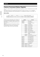
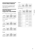
Control Control Camera Command Status Register This camera complies with IIDC 1394-based Digital Camera Specification, Version 1.31 (hereinafter referred to as IIDC v1.31). The standards document can be purchased from 1394TA (the 1394 Trade Association). As it is very helpful in understanding the explanations in this Technical Manual, we recommend that you purchase a copy of IIDC v1.31. Memory Map BusID NodeID Must be 1 Address used by the camera bbbbbbbb bbnnnnnn 11111111 11111111 11110000 11110000 00000000 00000000 1394 devices have a 64-bit address space. The upper 10 bits show the bus ID (0-1023), and the next six bits show the node ID (0-63). The IIDC standards require the next 20 bits to be 1. The remaining 28 bits can be allocated to the camera as addresses. The bus and node IDs may be changed if the topology is restructured because of bus reset, so only the least significant 32 address bits are shown in this Guide. Address Resister F0000000 Base address F0000400 ConfigROM area F0F00000 Base address for camera commands F0F00000 CameraInitialize F0F00100 Video Format Inq F0F00180 Video Mode Inq F0F00200 Frame Rate Inq F0F002E0 Format7 CSR Inq F0F00400 Basic Func Inq F0F00500 Feature Element Inq F0F00600 Isochronous Control register F0F0071C AbsoluteControlCSR Inq for Shutter F0F00800 FeatureControl F0F00970 AbsoluteControlCSR for Shutter F0F10000 Format7Mode0 CSR F0F11000 Format7Mode1 CSR F0F12000 Format7Mode2 CSR F0F13000 Format7Mode3 CSR F0F30000 AccessControlRegister F0F40000 MemoryShotControl F0F50000 UserFreeMemory F0F60000 - F0F61FFC LookUpTable F0F62000 - F0F62020 Filter F0F63000 - F0F63024 AWB parameters F0F64000 - F0F64020 AE parameters 16
-
 1
1 -
2
-
3
-
4
-
5
-
6
-
7
-
8
-
9
-
10
-
 11
11 -
 12
12 -
 13
13 -
 14
14 -
 15
15 -
 16
16 -
 17
17 -
 18
18 -
 19
19 -
 20
20 -
 21
21 -
22
-
23
-
24
-
25
-
26
-
27
-
28
-
29
-
30
-
31
-
32
-
33
-
34
-
35
-
36
-
37
-
38
 |
 |
