Sony XCDSX90 User Manual (XCDV60_V60CR_SX90_SX90CR_U100_U100CR_Technical_Manua - Page 7
Installation, Fitting the lens, Using a tripod, Connecting the camera cable
 |
View all Sony XCDSX90 manuals
Add to My Manuals
Save this manual to your list of manuals |
Page 7 highlights
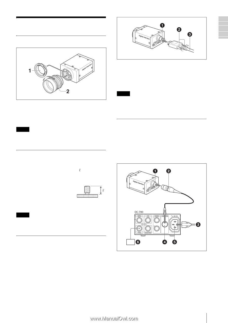
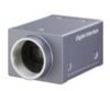
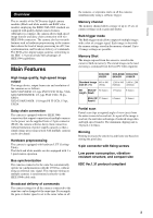
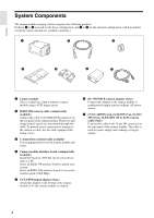
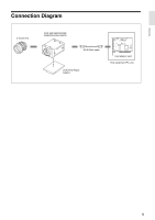
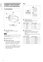
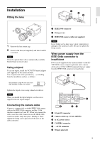
Installation Fitting the lens Overview 1 Remove the lens mount cap. 2 Screw in the lens (not supplied), and turn it until it is secured. Note Clean the optical filter with a commercially available blower brush to remove dust. Using a tripod To use the tripod, install the VCT-ST70I tripod adaptor (not supplied) on the camera module. Use a tripod screw with a protrusion ( ) extending from the installation surface, as follows: 1 IEEE1394b connector 2 Fixing screws 3 IEEE1394b camera cable (not supplied) Note Loose fixing screws may cause a poor connection or damage to the camera or cable. Be sure to tighten the fixing screws. When power supply from the IEEE1394b connector is insufficient Power can be supplied to the camera module via the DC700/700CE camera adaptor (optional) and a camera cable such as CCXC-12P05N (optional) if power supply from the IEEE1394b connector is insufficient. ISO standard: Length 4.5 mm to 5.0 mm ASA standard: Length 0.197 inches Tighten the tripod screws using a hand screwdriver. Note When you install the tripod adaptor, use the screws supplied with the tripod adaptor. Connecting the camera cable Connect a commercially available IEEE1394b camera cable to the IEEE1394b connector and the 1394b interface connector of your PC. When you connect the cable, insert the cable connector into the IEEE1394b connector until it snaps into place, holding it. Then, tighten the fixing screws placed on both sides of the cable connector. 1 12-pin I/O connector 2 Camera cable (e.g. CCXC-12P05N) 3 to AC power source 4 CAMERA connector 5 ~ AC IN connector 6 Trigger generator 7
-
 1
1 -
 2
2 -
 3
3 -
 4
4 -
 5
5 -
 6
6 -
 7
7 -
 8
8 -
 9
9 -
 10
10 -
 11
11 -
 12
12 -
13
-
14
-
15
-
16
-
17
-
18
-
19
-
20
-
21
-
22
-
23
-
24
-
25
-
26
-
27
-
28
-
29
-
30
-
31
-
32
-
33
-
34
-
35
-
36
-
37
-
38
 |
 |