Sony XCDSX90 User Manual (XCDV60_V60CR_SX90_SX90CR_U100_U100CR_Technical_Manua - Page 26
Control of Sony’s Unique Features, LUT (LookUp Table)
 |
View all Sony XCDSX90 manuals
Add to My Manuals
Save this manual to your list of manuals |
Page 26 highlights
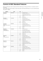
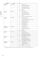
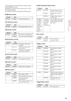
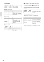
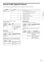
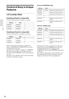
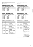
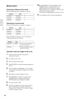
Control Control of Sony's Unique Features LUT (LookUp Table) Enabling writing the Lookup table Write the following three commands in sequence. Address F0F30000 F0F30004 F0F30008 Data 08004600 0030FFFF 80000000 Disabling writing the Lookup table Write the following three commands in sequence. Address F0F30000 F0F30004 F0F30008 Data 08004600 0030FFFF 00000000 When writing of the Lookup table is enabled, the addresses 0xF0F60000 to 0xF0F61FFC that store the Lookup table become open. The table has two channels. Channel 0 is in EEPROM write mode, and channel 1 is in RAM write mode. The table written in EEPROM is read out when Gamma is set to 3. The table written in RAM is directly reflected to images regardless of the Gamma setting. Channel 0 (EEPROM mode) Address F0F60000 F0F60004 F0F60008 : F0F60FF8 F0F60FFC Data Any data : Output data when input data is 0. Output data when input data is 1. Output data when input data is 2. Output data when input data is 0x3FE. Output data when input data is 0x3FF. Channel 1 (RAM mode) Address F0F61000 F0F61004 F0F61008 : F0F61FF8 F0F61FFC Data Any data : Output data when input data is 0. Output data when input data is 1. Output data when input data is 2. Output data when input data is 0x3FE. Output data when input data is 0x3FF. Although block writing is applicable for either mode, transfer the next data in EEPROM mode only after confirming that the previous writing has been completed, because writing in EEPROM mode requires a long time. The common Lookup table is used for both the 16-bit mode and 8-bit mode. For the 8-bit mode, the most significant 8 bits of the 10 bits will handle data. 26
-
 1
1 -
2
-
3
-
4
-
5
-
6
-
7
-
8
-
9
-
10
-
11
-
12
-
13
-
14
-
15
-
16
-
17
-
18
-
19
-
20
-
 21
21 -
 22
22 -
 23
23 -
 24
24 -
 25
25 -
 26
26 -
 27
27 -
 28
28 -
 29
29 -
 30
30 -
 31
31 -
32
-
33
-
34
-
35
-
36
-
37
-
38
 |
 |
