Sony XCDSX90 User Manual (XCDV60_V60CR_SX90_SX90CR_U100_U100CR_Technical_Manua - Page 4
System Components
 |
View all Sony XCDSX90 manuals
Add to My Manuals
Save this manual to your list of manuals |
Page 4 highlights
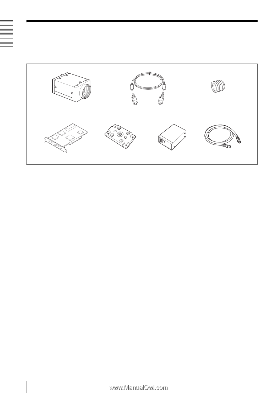
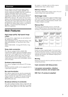
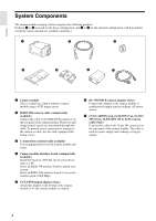
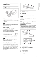
Overview System Components The camera module imaging system comprises the following products. Products 1 to 4 are used for the basic configuration, and 1 to 7 for the optional configuration. (All the products except the camera module are available separately.) 1 2 3 4 5 6 7 1 Camera module This is a small-size, high-resolution, camera module using a CCD image sensor. 2 IEEE1394b camera cable (commercially available) Connect this cable to the IEEE1394b connector on the rear panel of the camera module. The power and image/control signals are transmitted through this cable. To prevent a poor connection or damage to the camera or cable, use the cable equipped with fixing screws. 3 C-mount lens (commercially available) Use an appropriate lens for the camera module and usage. 4 Camera module interface board (commercially available) Install the board in a PCI bus slot of a host device such as a PC. Select an IEEE1394 interface board to match your system. Select an IEEE1394b interface board if you use the transfer speed of 800 Mbps. 5 VCT-ST70I tripod adaptor (Sony) Attach this adaptor to the bottom of the camera module to fix the camera module to a tripod. 6 DC-700/700CE camera adaptor (Sony) Connect this adaptor to the camera module to enable power supply from an ordinary AC power source. 7 CCXC-12P02N (2 m, 6.6 ft)/05N (5 m, 16.4 ft)/ 10N (10 m, 32.8 ft)/25N (25 m, 82 ft) camera cable (Sony) Connect this cable to the 12-pin I/O connector on the rear panel of the camera module. The cable is used for power supply and exchange of trigger signals. 4
-
 1
1 -
 2
2 -
 3
3 -
 4
4 -
 5
5 -
 6
6 -
 7
7 -
 8
8 -
 9
9 -
 10
10 -
11
-
12
-
13
-
14
-
15
-
16
-
17
-
18
-
19
-
20
-
21
-
22
-
23
-
24
-
25
-
26
-
27
-
28
-
29
-
30
-
31
-
32
-
33
-
34
-
35
-
36
-
37
-
38
 |
 |