Stihl FSA 90 R Instruction Manual - Page 17
Mounting the Loop Handle, Mounting the Deflector
 |
View all Stihl FSA 90 R manuals
Add to My Manuals
Save this manual to your list of manuals |
Page 17 highlights
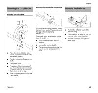
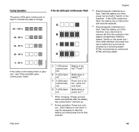
Mounting the Loop Handle Adjusting and Securing the Loop Handle English Mounting the Deflector 3988BA001 KN 0000-GXX-0571-A0 3988BA039 KN Mounting the Loop Handle 7 7 8 8 4 3 5 6 1 1 N Place the clamp (3) in the loop handle (4) and position them both against the shaft (5). N Position the clamp (6) against the shaft. N Line up the holes. N Fit washers (8) on the screws (7) and insert the screws in the holes. Fit the square nuts (1) and screw them down as far as stop. N Go to "Adjusting and Securing the Loop Handle". A 4 1 2 The loop handle can be adjusted to suit the height and reach of the operator and the application by changing distance "A". Distance A when using mowing heads: Max. 30 cm (12 in) N Slide the handle to the required position. N Line up the loop handle (4). N Tighten down the screws so that the handle cannot be rotated on the shaft. N Position the deflector against the motor housing. N Push hooks (1) on deflector into the recesses in the motor housing. N Insert the screw (2) and tighten it down firmly. FSA 90 R 15
-
 1
1 -
2
-
3
-
4
-
5
-
6
-
7
-
8
-
9
-
10
-
11
-
 12
12 -
 13
13 -
 14
14 -
 15
15 -
 16
16 -
 17
17 -
 18
18 -
 19
19 -
 20
20 -
 21
21 -
 22
22 -
23
-
24
-
25
-
26
-
27
-
28
-
29
-
30
-
31
-
32
-
33
-
34
-
35
-
36
-
37
-
38
-
39
-
40
-
41
-
42
-
43
-
44
-
45
-
46
-
47
-
48
-
49
-
50
-
51
-
52
-
53
-
54
-
55
-
56
-
57
-
58
-
59
-
60
-
61
-
62
-
63
-
64
-
65
-
66
-
67
-
68
-
69
-
70
-
71
-
72
-
73
-
74
-
75
-
76
 |
 |
