Sub-Zero BI-36S Built-In Installation Guide - Page 12
Site Preparation, Electrical Requirements
 |
View all Sub-Zero BI-36S manuals
Add to My Manuals
Save this manual to your list of manuals |
Page 12 highlights
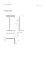
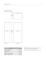
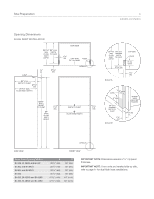
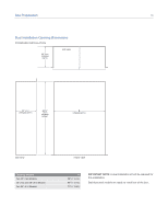
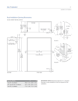
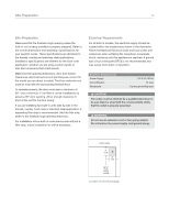
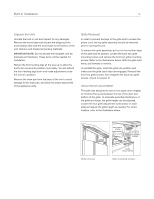
Site Preparation 12 Site Preparation Make sure that the finished rough opening where the built-in unit is being installed is properly prepared. Refer to the overall dimensions and installation specifications for your specific model. These specifications are identical for the framed, overlay and stainless steel applications. Installation specifications are different for the flush inset application, whether you are using custom panels or Sub-Zero accessory flush inset panels. Make sure the opening dimensions, door and drawer clearances, electrical service and plumbing are correct for the model you are about to install. The floor under the unit must be level with the surrounding finished floor. To operate properly, the door must open a minimum of 90°. Use a minimum 3" (76) filler in corner installations to assure a 90° door opening. Allow enough clearance in front of the unit for full door swing. If you are installing two built-in units side by side in the framed, overlay, flush inset or stainless steel application, a separating filler strip is recommended. Add the filler strip width to the finished rough opening dimension. For installation of two built-in units side by side without a filler strip, a dual installation kit will be necessary. Electrical Requirements For all built-in models, the electrical supply should be located within the shaded area shown in the illustration. Follow the National Electrical Code and local codes and ordinances when installing the receptacle. A separate circuit, servicing only this appliance is required. A ground fault circuit interrupter (GFCI) is not recommended and may cause interruption of operation. Electrical Requirements Power Supply Circuit Breaker Receptacle 115 V AC, 60 Hz 15 amp 3-prong grounding-type The outlet must be checked by a qualified electrician to be sure that it is wired with the correct polarity. Verify that the outlet is properly grounded. Do not use an extension cord or two-prong adapter. Do not remove the power supply cord ground prong. FRONT VIEW 7" (178) E 6" (152) 751/2" (1918) FROM FLOOR Location of electrical supply.
-
 1
1 -
2
-
3
-
4
-
5
-
6
-
 7
7 -
 8
8 -
 9
9 -
 10
10 -
 11
11 -
 12
12 -
 13
13 -
 14
14 -
 15
15 -
 16
16 -
 17
17 -
18
-
19
-
20
-
21
-
22
-
23
-
24
-
25
-
26
-
27
-
28
-
29
-
30
-
31
-
32
-
33
-
34
-
35
-
36
-
37
-
38
-
39
-
40
 |
 |
