Sub-Zero BI-36S Built-In Installation Guide - Page 26
Panel Installation, Overlay Panels - bi 36r
 |
View all Sub-Zero BI-36S manuals
Add to My Manuals
Save this manual to your list of manuals |
Page 26 highlights
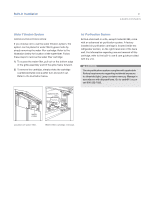
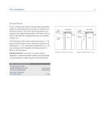
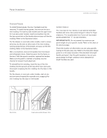
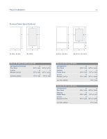
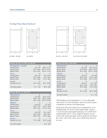
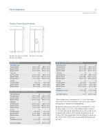
Panel Installation 26 Overlay Panels If your customer has chosen an overlay design application, make sure that the panels you are about to install match dimensions listed in the overlay panel specifications on pages 28-29. Additional panel design information can be found in the Sub-Zero design guide and on our website, subzero.com. IMPORTANT NOTE: The size of the overlay panel is critical. It must fit over the door frame. Also, do not exceed the maximum per panel weight for your specific model. Refer to the chart below. Overlay models are shipped without handle hardware. The cabinet manufacturer or designer will need to provide handle hardware to match the overall decorating scheme. To install overlay panels, first remove the door trim molding. For side-by-side models and the upper door for over-and-under models, insert a screwdriver tip into the top corner slot on the handle side and pop out the trim molding. Remove the screws and frame. For the drawer on over-and-under models, insert a screwdriver tip into the slot on either side of the trim molding running along the top of the drawer and pop out the trim molding. Remove the screws and frame. Refer to the illustrations on page 23. Sub-Zero allows a 1/4" (6) space to slide the backing material into place in the frame. If your material is thicker than a 1/4" (6), either rout an edge around the panel to get a proper fit or mount the decorative overlay panel on a sheet of 1/4" (6) thick material and insert the backing material into the channel. Overlay Panel Requirements MAX WEIGHT PER PANEL BI-36R, BI-36RG and BI-36F All Other Overlay Models Grille Panel MIN PANEL THICKNESS All Overlay Panels 75 lbs (34 kg) 50 lbs (23 kg) 13 lbs (6 kg) 5/8" (16) You must allow for .10" (3) space between the backer board and the decorative panel, so the panel will slide easily into the door frame. The illustrations below provide a cross section view of the three-panel assembly, showing placement of the trim and a rear view of the three-panel assembly with critical dimensions, standard for all built-in models. Install the handle hardware before inserting the panel. We recommend larger D-style pulls. The use of small, onepiece knobs is not recommended. If you use screws with thick heads, you will need to countersink the screws into the backer panel before sliding the assembly into place. Slide the panel into the frame on the door. With the panel in position, replace the frame end. Make sure the panel is inserted completely into the channel for proper fit and alignment. To reinstall the trim molding on side-by-side models and the upper door for over-and-under models, insert the top of the trim molding into the grooves at the top of the door and work downward, snapping the trim molding into the clips on the frame. For the drawer on over-and-under models, start at one end and move towards the opposite end, snapping the trim molding into the clips on the frame. SPACER PANEL OVERLAY PANEL BACKER PANEL TRIM 5/16" (8) min 1/8" (3) Panel assembly cross section. OVERLAY PANEL SPACER PANEL BACKER PANEL 3/4" (19) typical .10" (3) 1/4" (6) Panel assembly rear view.
-
 1
1 -
2
-
3
-
4
-
5
-
6
-
7
-
8
-
9
-
10
-
11
-
12
-
13
-
14
-
15
-
16
-
17
-
18
-
19
-
20
-
 21
21 -
 22
22 -
 23
23 -
 24
24 -
 25
25 -
 26
26 -
 27
27 -
 28
28 -
 29
29 -
 30
30 -
 31
31 -
32
-
33
-
34
-
35
-
36
-
37
-
38
-
39
-
40
 |
 |
