Sub-Zero BI-36S Built-In Installation Guide - Page 16
Built-In Installation, Unpack the Unit, Grille Removal
 |
View all Sub-Zero BI-36S manuals
Add to My Manuals
Save this manual to your list of manuals |
Page 16 highlights
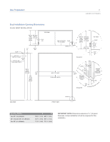
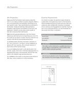
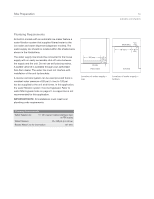
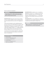
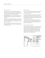
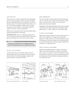
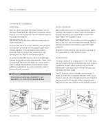
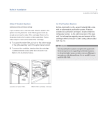
Built-In Installation 16 Unpack the Unit Uncrate the built-in unit and inspect for any damages. Remove the wood base and discard the shipping bolts and brackets that hold the wood base to the bottom of the unit. Remove and discard all packing materials. IMPORTANT NOTE: Do not discard the kickplate, anti-tip brackets and hardware. These items will be needed for installation. Retract the front leveling legs all the way up to allow the unit to be moved into position more easily. You will extend the front leveling legs down and make adjustments once the unit is in position. Remove the drain pan from the base of the unit to avoid damage to the drain pan, and allow for proper placement of the appliance dolly. Grille Removal In order to prevent damage to the grille and to access the power cord, the top grille assembly should be removed prior to moving the unit. To remove the grille assembly, pull out on the bottom edge of the grille and tilt upward. Loosen the back two grille mounting screws and remove the front two grille mounting screws. Refer to the illustrations below. With the grille held firmly, pull forward to remove. To reinstall the grille, insert the grille into position and make sure the grille catch tabs are engaged. Reinstall the front two grille screws, then retighten the back two grille screws. Check for proper fit. GRILLE HEIGHT ADJUSTMENT The grille was designed to rest on the upper door hinge(s) to minimize the reveal between the top of the door and bottom of the grille. To eliminate potential interference of the grille and hinge, the grille height can be adjusted. Loosen the four grille adjustment screws (two on each side) and adjust the grille height as needed. For screw location, refer to the illustration below. Grille removal. BACK GRILLE SCREW LOCATION OF GRILLE ADJUSTMENT SCREWS FRONT GRILLE SCREW Grille mounting screws.
-
 1
1 -
2
-
3
-
4
-
5
-
6
-
7
-
8
-
9
-
10
-
 11
11 -
 12
12 -
 13
13 -
 14
14 -
 15
15 -
 16
16 -
 17
17 -
 18
18 -
 19
19 -
 20
20 -
 21
21 -
22
-
23
-
24
-
25
-
26
-
27
-
28
-
29
-
30
-
31
-
32
-
33
-
34
-
35
-
36
-
37
-
38
-
39
-
40
 |
 |
