Sub-Zero BI-36S Built-In Installation Guide - Page 18
Level the Unit, Built-In Installation, Door Adjustment
 |
View all Sub-Zero BI-36S manuals
Add to My Manuals
Save this manual to your list of manuals |
Page 18 highlights
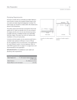
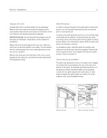
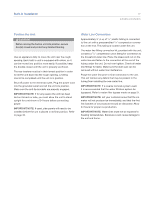
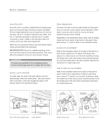
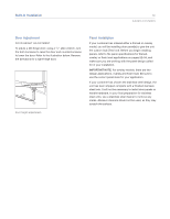
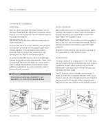
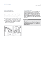
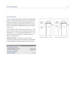
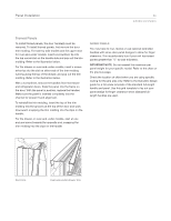
Built-In Installation 18 Level the Unit Once the unit is in position, extend the front leveling legs down by turning the legs clockwise to adjust the height. The rear height adjustment can be made from the front of the base. Use a 3/8" socket to adjust the rear rollers. Turn the 3/8" hex bolt clockwise to raise the unit or counterclockwise to lower it. Refer to the illustration below for location of the rear roller base adjustment. When the unit is properly leveled, door and drawer adjustments are less likely to be necessary. IMPORTANT NOTE: Be sure to reference leveling of the unit to the floor and not surrounding cabinetry. This could affect the operation of the unit, such as door closing. To reduce the possibility of the unit tipping forward, the front leveling legs must be in contact with the floor. INSTALL LIGHT DIFFUSER To install, align the slots of the light diffuser onto the bracket pegs under the control panel. Then pull forward fully so the tabs on the slots engage the pegs on the bracket. Refer to the illustration below. Door Adjustment The doors for built-in side-by-side models and the upper door on over-and-under models can be adjusted in three ways: in and out, side to side tilt, and up and down (except over-and-under models). Regardless of the adjustment being made, start by slightly loosening the two upper hinge bolts on the upper hinge plate using a 1/2" wrench. Refer to the illustration below. IN AND OUT ADJUSTMENT Refer to the illustration below for location of the bolt for in and out door adjustment. To adjust a left-hinge door; using a 5/32" allen wrench, turn the bolt clockwise to bring the handle side of the door inward, and counterclockwise to move the handle side of the door outward. Reverse the directions for a right-hinge door. SIDE TO SIDE TILT ADJUSTMENT Refer to the illustration below for location of the bolt for side to side tilt door adjustment. To adjust a left-hinge door; using a 3/8" wrench, turn the bolt clockwise to raise the handle side of the door up and counterclockwise to tilt the handle side of the door down. Reverse the directions for a right-hinge door. FRONT LEVELING LEG REAR ADJUSTMENT PEG SLOT Rear roller base adjustment. Light diffuser. UPPER HINGE BOLTS IN AND OUT ADJUSTMENT Upper hinge bolts. SIDE TO SIDE TILT ADJUSTMENT Door adjustment bolts.
-
 1
1 -
2
-
3
-
4
-
5
-
6
-
7
-
8
-
9
-
10
-
11
-
12
-
 13
13 -
 14
14 -
 15
15 -
 16
16 -
 17
17 -
 18
18 -
 19
19 -
 20
20 -
 21
21 -
 22
22 -
 23
23 -
24
-
25
-
26
-
27
-
28
-
29
-
30
-
31
-
32
-
33
-
34
-
35
-
36
-
37
-
38
-
39
-
40
 |
 |
