TASCAM DA-6400 DA-6400dp Owners Manual Addendum V2.20 - Page 7
Procedures to enable cascade operation
 |
View all TASCAM DA-6400 manuals
Add to My Manuals
Save this manual to your list of manuals |
Page 7 highlights
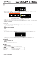
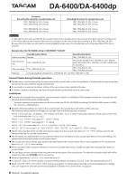
DA-6400/DA-6400dp Procedures to enable cascade operation Audio clock synchronization is necessary for cascade connections and connecting multiple DA-6400 units. See step 4 below for details about audio clock synchronization. 1. Set CASCADE MODE to ON on all units. 2. Set the CASCADE ID of one unit to MASTER , and set the other unit to SLAVE-01. 3. Connect all the units to the same network. When connecting to a network that has a DHCP server or when only the DA-6400 and a hub are connected in a network that does not have a DHCP server, set the IP SETUP MODE item to AUTO on the NETWORK menu page. When computers or devices other than DA-6400 units are connected on a network that does not have a DHCP server and only the DA-6400 and a hub are connected, set the IP SETUP MODE item to STATIC on the NETWORK menu page. Also set the IP ADDR of all devices so that the same segments have different values. Example of settings when the network does not have a DHCP server CASCADE ID MASTER SLAVE-01 MODE STATIC IP ADDR 192.168.100.100 192.168.100.101 SUBNET 255.255.255.0 Connection example Gigabit hub MASTER unit WORD IN Clock generator SLAVE-01 unit WORD THRU WORD IN Connections for cascade synchronization When setting and connections are completed for 1-3, implementation of the cascade connection will automatically start. When all the cascade connections are established, OK and the number of cascade connected units will appear in the CASCADE STATUS line on the CASCADE menu page of every device. In addition, the cascade setting indicator will appear on the Home Screen. Furthermore, unless there is an error or other issue, the INFO indicator will light blue. 4. Audio clock synchronization requires routing that is separate from the cascade connections. For this reason, all the units should be connected so that audio clock can be synchronized. Connection example: Using an external word clock for master clock Gigabit hub MASTER unit WORD IN Clock generator SLAVE-01 unit WORD THRU WORD IN Connections for audio clock synchronization 7 TASCAM DA-6400/DA-6400dp
-
 1
1 -
 2
2 -
 3
3 -
 4
4 -
 5
5 -
 6
6 -
 7
7 -
 8
8 -
 9
9 -
 10
10 -
 11
11 -
 12
12 -
13
-
14
-
15
-
16
-
17
-
18
-
19
-
20
-
21
-
22
-
23
-
24
-
25
-
26
-
27
-
28
-
29
-
30
-
31
-
32
-
33
-
34
-
35
-
36
 |
 |
