TP-Link 10GE T1700G-28TQ V1 Installation Guide - Page 13
Stacking Using SFP+ Port
 |
View all TP-Link 10GE manuals
Add to My Manuals
Save this manual to your list of manuals |
Page 13 highlights
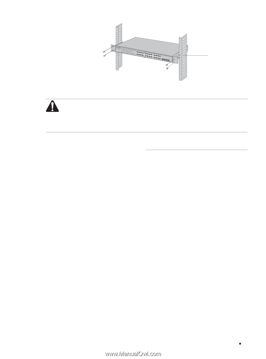
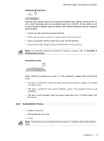
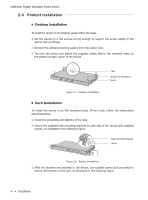
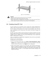
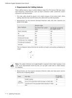
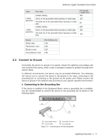
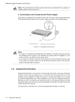
JetStream Gigabit Stackable Smart Switch Rack Figure 2-3 Rack Installation Caution: ■■ Please set 5-10cm gaps around the device for air circulation. ■■ Please avoid any heavy thing placed on the device. ■■ Please mount devices in sequence from the bottom to top of the rack and ensure a certain clearance between devices for the purpose of heat dissipation. 2.5 Stacking Using SFP+ Port You can connect up to 6 switches to form a stack with a single management IP address. Follow the steps below to connect the switches and configure the stack ports, then the switches will automatically elect a master unit and establish a stack. Once the stack is established, you can use any port of any switch in the stack to manage the stack system. Any SFP+ ports (Port 25-28) on the front panel can be used for stacking. Port 25-26 belong to Stack Port Group 0 and Port 27-28 belong to Stack Port Group 1. Since stack capability cannot be enabled in the two groups simultaneously, you can enable stack feature in either Group 0 or Group 1. Here is an example of a recommended configuration that uses three rack-mounted switches to form a full-ring stack. Configuration and Connection 1. Log on to the GUI of each switch, go to Stack→Stack Management→Stack Config page to enable the Stack Capability of port 25 and 26 (port 1/0/25 and 1/0/26 on the GUI). Remember to click Apply after the configuration. 2. Power off the switches, and then use the 10G SFP+ cable (TXC432-CU1M/TXC432CU3M of TP-LINK for example) to connect each switch to the next in a cascade. Finally, connect the last switch in the stack to the first switch, thus forming a ring topology as Figure 2-4 shows. The ring topology system provides redundancy and resiliency to the stack. Installation 08
-
 1
1 -
2
-
3
-
4
-
5
-
6
-
7
-
 8
8 -
 9
9 -
 10
10 -
 11
11 -
 12
12 -
 13
13 -
 14
14 -
 15
15 -
 16
16 -
 17
17 -
 18
18 -
19
-
20
-
21
-
22
-
23
-
24
-
25
-
26
-
27
-
28
 |
 |