TP-Link T1500G-10PS T1500G-10PSUN V1 User Guide - Page 90
MSTP Instance
 |
View all TP-Link T1500G-10PS manuals
Add to My Manuals
Save this manual to your list of manuals |
Page 90 highlights
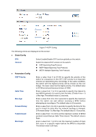
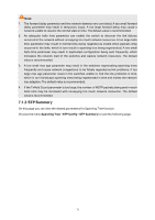
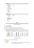
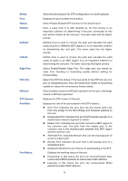
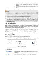
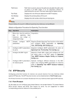
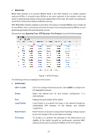
LAG: Blocking: In this status the port can only receive BPDU packets. Disconnected: In this status the port is not participating in the STP. Displays the LAG number which the port belongs to. Note: 1. Configure the ports connected directly to terminals as edge ports and enable the BPDU protection function as well. This not only enables these ports to transit to forwarding state rapidly but also secures your network. 2. All the links of ports in a LAG can be configured as point-to-point links. 3. When the link of a port is configured as a point-to-point link, the spanning tree instances owning this port are configured as point-to-point links. If the physical link of a port is not a point-to-point link and you forcibly configure the link as a point-to-point link, temporary loops may be incurred. 7.3 MSTP Instance MSTP combines VLANs and spanning tree together via VLAN-to-instance mapping table (VLAN-to-spanning-tree mapping). By adding MSTP instances, it binds several VLANs to an instance to realize the load balance based on instances. Only when the switches have the same MST region name, MST region revision and VLAN-to-Instance mapping table, the switches can be regarded as in the same MST region. The MSTP Instance function can be implemented on Region Config, Instance Config and Instance Port Config pages. 7.3.1 Region Config On this page you can configure the name and revision of the MST region Choose the menu Spanning Tree→MSTP Instance→Region Config to load the following page. Figure 7-7 Region Config The following entries are displayed on this screen: Region Config Region Name: Revision: Create a name for MST region identification using up to 32 characters. Enter the revision from 0 to 65535 for MST region identification. 80
-
 1
1 -
2
-
3
-
4
-
5
-
6
-
7
-
8
-
9
-
10
-
11
-
12
-
13
-
14
-
15
-
16
-
17
-
18
-
19
-
20
-
21
-
22
-
23
-
24
-
25
-
26
-
27
-
28
-
29
-
30
-
31
-
32
-
33
-
34
-
35
-
36
-
37
-
38
-
39
-
40
-
41
-
42
-
43
-
44
-
45
-
46
-
47
-
48
-
49
-
50
-
51
-
52
-
53
-
54
-
55
-
56
-
57
-
58
-
59
-
60
-
61
-
62
-
63
-
64
-
65
-
66
-
67
-
68
-
69
-
70
-
71
-
72
-
73
-
74
-
75
-
76
-
77
-
78
-
79
-
80
-
81
-
82
-
83
-
84
-
 85
85 -
 86
86 -
 87
87 -
 88
88 -
 89
89 -
 90
90 -
 91
91 -
 92
92 -
 93
93 -
 94
94 -
 95
95 -
96
-
97
-
98
-
99
-
100
-
101
-
102
-
103
-
104
-
105
-
106
-
107
-
108
-
109
-
110
-
111
-
112
-
113
-
114
-
115
-
116
-
117
-
118
-
119
-
120
-
121
-
122
-
123
-
124
-
125
-
126
-
127
-
128
-
129
-
130
-
131
-
132
-
133
-
134
-
135
-
136
-
137
-
138
-
139
-
140
-
141
-
142
-
143
-
144
-
145
-
146
-
147
-
148
-
149
-
150
-
151
-
152
-
153
-
154
-
155
-
156
-
157
-
158
-
159
-
160
-
161
-
162
-
163
-
164
-
165
-
166
-
167
-
168
-
169
-
170
-
171
-
172
-
173
-
174
-
175
-
176
-
177
-
178
-
179
-
180
-
181
-
182
-
183
-
184
-
185
-
186
-
187
-
188
-
189
-
190
-
191
-
192
-
193
-
194
-
195
-
196
-
197
-
198
-
199
-
200
-
201
-
202
-
203
-
204
-
205
-
206
-
207
-
208
-
209
-
210
-
211
-
212
-
213
-
214
-
215
-
216
-
217
-
218
-
219
-
220
-
221
-
222
-
223
-
224
-
225
-
226
-
227
-
228
-
229
-
230
-
231
-
232
-
233
-
234
-
235
-
236
-
237
-
238
-
239
-
240
-
241
-
242
 |
 |
